What's new
What's new

Matsuura MX-520 Tool point control. Kinematic parameters and thermal growth.

James K

Plastic
Joined
Sep 22, 2015
Matsuura MX-520 with Fanuc 31i

Is there a way to compensate the machine kinematics parameters for thermal growth?

The machine has scales on all axes but we are seeing a consistent growth of .0016 inch every day in the Y axis and at least .0005 in x. This shift in the table position makes the kinematics in the control (parameters 19700 etc) incorrect. Thus parts are not machined accurately.

Is there a way to quick way to compensate for this?
Are there other thermal comps on this machine we should look into to solve the problem?

When using inverse time I just re-indicate the center of rotaries set G54 and push go. I do not see a way to accomplish this when using TCP, because it relies on the kinematic parameters for all calculations.

Thank you
 
Talk to Renishaw about the Fanuc T-T auto update version of AXISET PN/ A5642-4120. Once you have it set up you can just run their macro and it will automatically update the offsets on the machine to where everything has grown to.

I'm just in the process of trying it out on my machine but I've seen it running on a Mikron and they just had the machine bring in the tooling ball pallet every 2 hours and update everything.
 
Use G54.4 - G54.4 (WSEC) is used to adjust for work setting error and will compensate correctly for the Kinematics. Assuming you are using center of rotation as your programming zero you should make sure that G54 matches the 19700 parameters and then adjust the G54.4 for the X and Y as the day goes on.

Depending on your processing and time of process the thermal growth should be fairly predictable and can therefore be adjusted for over the course of the day. Otherwise you indicate each part individually, or you can invest in a good In Process Probe like a Renishaw OMP-400 to locate each part when trying to hold tight tolerances. It sounds like the .0016" is the maximum so the error on any given part would be much smaller?

Remember that thermal growth is due to thermal changes in either the Environment or in the Process so the best way to beat it is to try to eliminate these changes.

Hope this helps! :)
 
"Talk to Renishaw about the Fanuc T-T auto update version of AXISET PN/ A5642-4120"

Matsuura provides this same feature called EZ-5.
 
I wonder if the scales are not configured correctly ...they should be compensating for most of that movement.

I have the Renishaw axiset for my two 5 axis machines but dont use it throughout the day. Scales take care of most of the thermal expansion.
 
Matsuura MX-520 with Fanuc 31i

Is there a way to compensate the machine kinematics parameters for thermal growth?

The machine has scales on all axes but we are seeing a consistent growth of .0016 inch every day in the Y axis and at least .0005 in x. This shift in the table position makes the kinematics in the control (parameters 19700 etc) incorrect. Thus parts are not machined accurately.

Is there a way to quick way to compensate for this?
Are there other thermal comps on this machine we should look into to solve the problem?

When using inverse time I just re-indicate the center of rotaries set G54 and push go. I do not see a way to accomplish this when using TCP, because it relies on the kinematic parameters for all calculations.

Thank you

I think you are mixing terms ^, (inverse time is a feed mode, maybe you mean using it in just 4 axis motion?) but maybe not? Are you warming up the machine in the morning, or at beginning of the shift? I would not think a Matsuura would move this much, but I don't know. I am curious because we looked at the machine, but ultimately it was just "too" much machine for what we needed, or read that as too much money LoL! Anyways, our UMC does not move that much (at least the .0016 in Y), as far as a static G54 work offset. IE, if I pick up a vise edge it stays put more or less, can't speak too much about kinematics as what I have done was not inspected to that level of precision. Although I will say using the renishaw probe routine to pick up center of rotation I have done 3 or 4 times now and all numbers were less than .001 between install last year and now.
 
How stable is the environment that your machine is in? Big ambient temperature swings throughout the day or pretty stable? If its say 60 deg in your building at 6am the 80 deg in the afternoon....you are gonna be chasing this forever. Not that it can't be overcome....tho it makes life more interesting than it should have to be.
 
Tell me if I am incorrect but WSEC for error in setting my part on the machine. My fixture is EXACTLY set on center of rotation (well darn close anyway). When the kinematic parameters do not match the position of the table I do not believe any error comp or work setting will help. My understanding is that the kinematic parameters must match the table position.
 
How stable is the environment that your machine is in? Big ambient temperature swings throughout the day or pretty stable? If its say 60 deg in your building at 6am the 80 deg in the afternoon....you are gonna be chasing this forever. Not that it can't be overcome....tho it makes life more interesting than it should have to be.

Shop has AC. Temp is within 3 degrees all day. We have been recording coolant temp, and casting temps in 3 spots. All temps are very stable through the day. I do not have easy access to internal components of the machine but that must be where most of the thermal distortion is coming from.
 
Shop has AC. Temp is within 3 degrees all day. We have been recording coolant temp, and casting temps in 3 spots. All temps are very stable through the day. I do not have easy access to internal components of the machine but that must be where most of the thermal distortion is coming from.

Yep. You're probably running into a minor deficiency in the machine layout. There's a reason the MAM isn't laid out like the MX.

Compare:

MAM72-63V
mam72_zpsmqmailah.jpg


NMV
nmv5000_zpsu3deozm3.jpg


Variaxis
i600_zps7slpypzw.jpg


Hermle
hermle_zpstriq2voj.jpeg


D500
ne3953-makino_D500_350_zpsjqrhctat.jpg


And then MX-520.
mx520_zpssim66f5v.png


Very nice machine, but definitely made some compromises in structure to reduce cost. There might be some thermal comp tweaking that could save the day?
 
Try leaving the machine in a warmup cycle when not in use. I run a speed of 250 and feed 25 ipm. I do this in a 4 axis matsuura when running tight tolerance jobs.
 
Yep. You're probably running into a minor deficiency in the machine layout. There's a reason the MAM isn't laid out like the MX.


Very nice machine, but definitely made some compromises in structure to reduce cost. There might be some thermal comp tweaking that could save the day?

Very nicely illustrated.
 
Leaving threads unresolved creates substantial FUD ?

This is not a "Rant" per se...

But It would be really really really really GREAT to know WT(heck) happened here ?


Did OP get resolution, and fixed the problem? [Or was the machine abandoned ?].


Was there an easy fix ? (like one of those really embarrassing "D'oh) type fixes ?


OR

IS there really a problem with spindle growth and general machine growth that for some reason is difficult to map out/ compensate for (even with scales) ?


Personally I think certain aspects of the Matsuura MX-520 design is really excellent from the aspect of small force loop (for a machine in its "class", you'd be hard pushed to improve upon it... So what's going on ? what happened? ???? ? But on the other hand the castings that are the thinnest and therefore susceptible to greatest heat change are also closest to main source of heat (spindle)… And the thicker castings thermally change more slowly ? Scales should take care of some of that without having to have heat sensors and complex compensation methods in the machine? Core cooled ball screws ?

_________________________________________________________________________________________________________


IME really good platforms products , systems and machines rarely end up on the second hand market... (if people really like them).

Also just underscores the need to have "Endings" to "Beginnings" as otherwise this thread turns from potentially useful actionable information to 100% FUD ?
 
Matsuura MX-520 with Fanuc 31i

Is there a way to compensate the machine kinematics parameters for thermal growth?

The machine has scales on all axes but we are seeing a consistent growth of .0016 inch every day in the Y axis and at least .0005 in x. This shift in the table position makes the kinematics in the control (parameters 19700 etc) incorrect. Thus parts are not machined accurately.

Is there a way to quick way to compensate for this?
Are there other thermal comps on this machine we should look into to solve the problem?

When using inverse time I just re-indicate the center of rotaries set G54 and push go. I do not see a way to accomplish this when using TCP, because it relies on the kinematic parameters for all calculations.

Thank you

I don't know why this bugs me so much other than I nearly pulled the trigger on a second hand one of these (really nice machine at killer price).

I think I have an idea as to what might be happening.

IF
(big if)… heat builds up in that righthand drive and support on the trunnion relative the left hand support* (as the left hand support does not have a drive system motor in it) i.e. by the usually and apocryphal 8 degrees Celsius temperature change oft cited by MTBs . Then according to my back of napkin / envelope math** then that support can move up to 50 micron (0.05 mm) 0.002" in the Y direction. That means the trunnion can pivot from the left side bearing if there is a 8 degree differential between the bearing housing and cast iron support on the right versus the left side. That pivot effectively in the XY plane would move the center of the table by 0.001" (ish)… AND the effective rotation of the table would be 3.6 arc seconds (roughly 0.001 degree (thousandths of a degree) (that's not so bad). Effectively the center point of table would creep outwards by 0.001" over a day or 8 degree temperature difference between left and right trunnion supports. The right hand support would expand in the Z direction by about 1/2 of the Y direction expansion from 8 degree Celsius temperature differential 20 micron and then pivoted from that left bearing would put you in the neighborhood of 3 tenths... ) 0.0003".

I'm thinking this should not be beyond the "wit of man" to comp but it's counter intuitive as its not a comp that is orthogonal to the scales / principal axes.


Dumb question here does the MX-520 have special cooling for the drive system and casting on the right hand side of the trunnion?

_________________________________________________________________________________________

* this also lends a certain amount of credence to twin drive trunnion based machines or ones that have "manic" cooling systems throughout. (But also makes me think a knuckle style machine won't pivot from differential thermal expansion (large bearing) and some of the most fast and fiendishly accurate 5 axis machines are small table 5 axis "knuckle" machines or completely symmetric trunnion machines. ) .

** Will check math again later.
 
If the shop has AC, and the spindle has a chiller, and the coolant tank has a chiller, and the ways have micron scales, then the situation is as good as it's gonna get. If I were running that I'd do a probe program after every part to find the new center(s) of rotation(s). And yeah cameraman, it's too bad most of the threads on here are inconclusive and lack follow up.

If a high end 5 axis machine like this can only work to 0.0015" over the day, I wonder how the really high end jig bore machines like Yasdas and Mitsui Seikis can hold within a micron over their envelope.

Apologies for length (will edit eventually).

I couldn't agree more ! :D


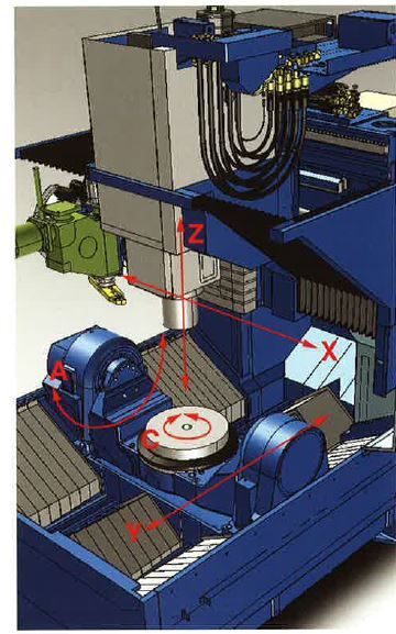
I think the trouble comes / one might get bitten on the arse, on a part like a large blisk with the trunnion tilted 45 to 60 degrees
... So by the time you make it all the way around your whole part is out of tolerance.


There are solutions to this... If heat building up in that big joint is a problem then next generation could circulate specific coolant through that joint (like they do for Direct drive motors and then send the warmer coolant to circulate around a beefed-up version of the left hand bearing on the trunnion and cast iron support. (A technique borrowed from "Rocket engineering"). That way the principal axis of the trunnion stays parallel to the X axis of the machine.


One hack for that (also) would be put a temparture sensor on the right support and have heating pads/ elements on the left support + controller … That would put the trunnion more square to the spindle and parallel to X. At least you would only have to compensate in the Y axis and normal amounts (more or less) in Z.


Another hack would be if your Blisk is out of tolerance in a predictable way then you could effectively deform all of the XYZ coordinates for the geometry for 12 hour deformation cycle, compensated for IF the machines thermally moves in non othrogonal yet repeatable ways during the cycle or during the day.Obviously much easier for in house engineering. Difficult to do with client's models etc. but might be worth a go. Effectively the rotated distortion + vector (pivot)from thermal differences in the machine (as stated by OP) would apply a spiral deformation (to a blisk) as well as progressively diminish the radius of the part by a certain amount. A counter deformation / spiral compensation could applied to the XYZ part coordinates and it should "neutralize" assuming repeatable thermal conditions.


So it IS a design "Element" that can be fixed. Doesn't have to be that way. Honestly I do like the small force loop on the ZY plane on the MX-520 and I like the near sub micron spindle that the Matsuura's have ( Maxxia thing they have going)+ Camplete.


There other ways to predictably compensate for that also... Just with Software (real time on a 1/2 decent control)... (probing during cycle and math that we have for other applications that (personally I would like to transfer to five axis machine( … But maybe I never get the chance to do that). I have to admit that's why the Okuma/OSP control has always interested me but seems there is a bit of a fire-wall to get to the more dynamic stuff (understandably so).


I agree probing cycles (if you have the right probe) for positional work makes absolute sense and to do like real machinists design IN reference surfaces to probe from during cycles.


I think also I'm slowly learning that a lot of 5 axis machines can ONLY be used in certain ways that the machine is originally intended for. I know that sounds stupid and obvious but I think amongst younger engineers there is this idea that Five axis = almost 3d printer at high tolerances and that's really not the case.


Comes back to the principal of "No free lunch" on certain machines.


… I probably would have pulled the trigger on the second hand Matsuura MX 520 (or even a new one) had it not been for this thread coupled with the fact that coincidently some of these machines were given up to the second hand market quite early on by really experienced and skillful machinists. [That left me scratching my head].

IF for example the problem is non orthogonal pivot from the left trunnion support that would not have bothered me in the least as I FEEL confident that I can map that one out.


It's difference between a foible or characteristic (like handling characteristics with cars and horses) that can be ironed out / or be corrected for with time and bit imagination and ingenuity versus something that is a Totally "Blind" unknown… That manifests itself into chin scratching FUD.


Like where is the actual source of the error. I only stumbled upon that idea from putting together some anecdotal pieces like lego bricks in my mind over a period of time. (Grey cells working in the background). But still not definitive but would be solvable.


The point being Knowing what an actual source of a problem is is much better than not knowing cuz then you can make the judgement call how to "Fix" that if you need to... Most people don't need to, or at least maybe the "Problem" is really not relevant to the type of work one has to do. There are no perfect machines but knowing what the tradeoff and strengths and weakness and inherent problems make it a LOT easier to make decisions.


Slowly I'm starting to understand why the HERMLE's are so good at what they do. No free lunch but some crafty design improvements I'm sure can put the MX-520 in a good sweet spot for the better part of a day.

____________________________________________________________________________

Long Story short: Any systematic error (as long as a machine has at least 1 really straight axis) I'm totally chill with even non linear and non-orthogonal problems … It's the non-systematic seemingly random problems and errors that get reported are a cause for concern.


I think that's what got OP's Goat he couldn't find the logic / seemed completely unresolvable by normal methods commonly available on the control. And it's really not obvious...
 
.....If a high end 5 axis machine like this can only work to 0.0015" over the day, I wonder how the really high end jig bore machines like Yasdas and Mitsui Seikis can hold within a micron over their envelope.

A Matsuura is a "commodity" Japanese 5 axis machine. Not comparable to truly high end machinery like Yasda and Mitsui. Not to say that a Matsuura is bad, just not in the same league as others.

Cameraman's comment above about single sided trunnion drive being a potential source of error is recognized by some builders. Makino drive their large trunnion machines from both ends with a single servo. The servo motor drives a cross shaft via timing belt to gear stacks running up both trunnion "ears".


Back
Top