KristianSilva
Aluminum
- Joined
- Nov 26, 2016
Hello,
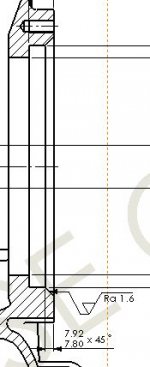
Im doing a job at the moment that is a 50Kg cast iron part, because of its weight and out of balance nature I want to mill the part complete (on VF3), but the part has toleranced O-ring chamfers (7.8-7.92mm x 45°) at the opening of a bores on both sides of the part, see picture below.

Measuring the chamfer on the second Op is no problem as I can take the part off the machine and measure using Faro arm and then just probe the part back in, but I need a way of measuring the chamfer while it is still on the machine during the first OP so I can bring the chamfer to size and avoid scrap.
I thought about doing a setup piece but this would be tricky as we are a production shop who use fixture plates so I cant easily just throw a vice on, plus this doesnt actually give me a way to measure the chamfer size.
Does anyone know of any measuring equipment that I can use to measure this? Or have any other suggestions on how I can?
At the moment the only idea I have is making a shallow test gauge type measuring gauge where the gauge locates in the bore and on the top face of the bore with the indicator pointing perpendicular to the chamfer face, then creating a known test piece (not on one of our production machines) to compare against.
Hope this makes sense, any questions just ask!
Im doing a job at the moment that is a 50Kg cast iron part, because of its weight and out of balance nature I want to mill the part complete (on VF3), but the part has toleranced O-ring chamfers (7.8-7.92mm x 45°) at the opening of a bores on both sides of the part, see picture below.

Measuring the chamfer on the second Op is no problem as I can take the part off the machine and measure using Faro arm and then just probe the part back in, but I need a way of measuring the chamfer while it is still on the machine during the first OP so I can bring the chamfer to size and avoid scrap.
I thought about doing a setup piece but this would be tricky as we are a production shop who use fixture plates so I cant easily just throw a vice on, plus this doesnt actually give me a way to measure the chamfer size.
Does anyone know of any measuring equipment that I can use to measure this? Or have any other suggestions on how I can?
At the moment the only idea I have is making a shallow test gauge type measuring gauge where the gauge locates in the bore and on the top face of the bore with the indicator pointing perpendicular to the chamfer face, then creating a known test piece (not on one of our production machines) to compare against.
Hope this makes sense, any questions just ask!


 )
) I just drill a hole some place on the part that is going to get machined away. Then I drill or circle mill a chamfer in that hole and measure it with my countersink measuring tool (or a tooling ball). At that point, I know that my chamfer tool Z height and radial compensation is set correctly and then I machine the chamfer in question. I have been doing that for twenty years and I haven't had a part rejected either internally (CMM) or by my customers.