What's new
What's new

Milltronics Partner 1F Intermittent Estop Error

npolanosky

Cast Iron
Joined
Apr 9, 2016
Location
USA, FL
I acquired a '93 milltronics Partner 1F for real cheap a few months ago intending to use it as a second op machine. The previous owner just didn't have an interest in mill work anymore (transitioning to EDM work only) said it worked fine, just needed a limit switch replaced, so I figured that would be a super easy fix. It sits on my floor for a month while I find time to wire it up (and realize I need to buck the 250v from the power company down to 220v- took care of that).

Finally got it powered up, replace the supposed failed limit switch (which tested fine actually), and it still shows the same alarm as it did before- 450: Estop has been pressed or machine is on a limit switch. Interestingly though, I can press reset and it will work for about 1 minute before triggering again. The less time I give it before resetting, the less time it takes to alarm, ranging from instantaneous to long enough to home it, jog a bit, and do a tool change or two. Everything else seems to work perfect.

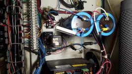
It'll alarm even if completely stationary and idle. I have checked the series-wired limit switches independently and also checked the entire string of them at the terminal block in the electrical cab- They don't indicate an open circuit and aren't intermittent. I ran a jumper across the entire set, from 6A (spindle fault) to 9 (Z limit IIRC). Still got an estop alarm, which rules out any broken wires or intermittent switches.

I can run the machine normally if I hold in the reset button (which keeps the latching enable relay hold on)

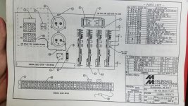
All I can figure is a component on a board, a bad relay, or a failing power supply. The electrical diagram is pretty simple, I'll attach it here shortly.

If anyone has an idea of what else to check, let me know. It seems like it has to be something simple tripping up the Estop alarm. Maybe thermal (overloaded/overheating linear power supply dropping out and then resetting?) or something attached to a capacitor, since the amount of time it will run is related to how long you wait before resetting it.

Milltronics support has been largely unresponsive (and I don't blame them, this machine is 25 years old and they haven't received a penny from me) so I'm hoping someone here has come across this issue before.

Pics and video of the issue incoming shortly.
 
It could be the relay, mine started buzzing and dropping out on occasion so I bought replacements off eBay and then it's worked ever since. There is also a resistor across the terminals of the big blue capacitors in the back. If that's shot, the machine will not run. Other thing I have run into with my Milltronics is the low voltage power supply, mine had a bad component and where it's supposed to supply positive 12V and negative 12V it was running 24V on one or the other (might be 15V, I can't remember for sure without going and looking). That would cause a problem with the servo drives and following error that would sometimes shut the machine down, especially if you tried to move very fast at all.

Hope some of that helps, just what I can think of off the top of my head.
 
Uploading the video now- You say the machine won't run if that resistor is shot. Hrm. I thought it just bled the voltage from the caps for safety after shutdown. Interesting. Mine is very much toast, but I got replacements in the mail today. I'll install one, that sure would be an easy an obvious fix. It looks like it was red at one point, but it's decidedly black now and the heat shrink is missing or crumbly over 70% of it's body.

I'm going to check part numbers for the relays and if they're all the same I'll swap the flood coolant relay for the enable relay since I don't have flood, only mist coolant. If that fixes it I'll buy some spares.

I'll check out the power supply too, I got 3 spares with it that they just tossed in the chip tray. I wonder if that's a sign that it tends to go through them. Not sure if any of them work (were they spares, or old ones that are cooked), but I guess I can always wire them up and test them outside the machine.
 
AHA. Maybe.

I looked closer at that resistor, and when I went to replace it I realized there are two- One going to a blue wire and going somewhere up top, and another going into a fuse and then to ground. Fuse is blown. Going to replace the resistors and that fuse and see where that gets me.
 
Resistor replaced, and fuse is replaced (home depot had the same one as was installed in stock)

Turned it on, machine seemed to work, and then it quit. Checked the fuse, and it was blown. It seems to go from the negative terminal of the big caps to the cap mounting thingy which is bolted to the cabinet (and therefore grounded, ja?)

Need to do some more actual work, will study the electrical diagrams and see if I can figure out whats going on here. The caps are 160VDC, the resistor is 10 ohms, the fuse that was present (and it's replacement) were 1A. If it's supposed to have current flowing all the time that does not compute...that would be 16A. Either the fuse is wrong or something is not working as intended.

Edit: Just looked closer at the diagram. The diagram indicates a 15A slow blow fuse near the caps. Physical location is slightly off, but it's close. No 1A fuse anywhere nearby. Maybe the old fuse was replaced with the wrong kind, and I just replaced the wrong one with the same wrong one. Might change it to a 3A of the same size and put my meter in line to see what it's pulling, even just for a few moments, before going to the bigger one. Don't want to fry anything more expensive than fuses if I don't have to.

Edit again, because I guess I'm thinking out loud now:
So if a 15A fuse is correct, there's no way that's actually the intended operating current or even close.
15A through a 10 ohm resistor at 160V means it would be dissipating 2.25KW. That's a freaking toaster, not a 10 watt resistor. The wires are about 18ga. A 1A fuse would limit it to the capacity of the 10W resistor, and slow blow would allow higher peak loads for a short time.

Hrm. I'll crack this eventually. Going to make sure there's not another fuse holder nearby before I match to the diagram, because there are technically two resistors coming off of the cap, and the 500 ohm is listed but the 10 ohm is not, and it does not show the fuse connecting to anything.
 
Are you sure that is a resistor and not a diode? Those caps are for the DC bus that runs the servo drives. There would have to be a rectifier somewhere.

Did I miss the diagram?
 
They're definitely resistors, but there is a bridge rectifier in the mix. After measuring voltages from the cap terminals to case ground, a buddy of mine and I are suspecting a bridge rectifier issue. I'm going to remove it and test it shortly, it's just a bit of an operation to do so due to a lack of connectors.

Have some diagrams and pictures in the mean time. The diagrams are a little open to interpretation; There are components present that do not exist in the diagrams, and there are components illustrated without connections drawn.
 

Attachments

  • 20181214_194908.jpg
    20181214_194908.jpg
    103.5 KB · Views: 492
  • 20181214_194836.jpg
    20181214_194836.jpg
    96.9 KB · Views: 290
  • 20181214_194805.jpg
    20181214_194805.jpg
    97.4 KB · Views: 320
  • 20181214_200643.jpg
    20181214_200643.jpg
    102.9 KB · Views: 210
Bridge rectifier appears to check out OK. Put 15.4vdc into the AC input, got 14.2v out on the DC output. Flipped polarity, same result. Did a diode check on all of them and they have the same resistance +/- a couple % and conduct the way they should and don't conduct in the other direction. My suspicion returns to a grounding issue with something.
 
Some more docs, in case anyone stumbles across this in the future.

Regardless of what the dealio is with that fuse, it didn't seem to change the behavior too much. I will try swapping to a 15a per the unclear diagram tomorrow. Biggest I have on hand right now is 3 amp.

(Edit: NOPE. Tried with the 3A. Fuse is fine, resistor notsomuch. Got a voltage reading, from capacitor gnd to case gnd I read 348VAC. Wat. Of course it blew, that's 12KW through a 10 ohm resistor. To be continued.)

I am going to verify the servo drives aren't complaining next. Their watchdogs are in the estop circuit, so since I have checked every other component of that circuit except the relays and watchdogs, I guess that's an obvious next move.

If the servos aren't alarming per their test points or leds or the watchdog circuit, I will check the relays. I don't think they're bad though, they do flip on and off as intended and the control is displaying the Estop output, not just randomly disabling the drives and stuff (which would give an excess error message I think)
 

Attachments

  • 20181215_000452.jpg
    20181215_000452.jpg
    96.5 KB · Views: 112
  • 20181215_000457.jpg
    20181215_000457.jpg
    90.3 KB · Views: 202
  • 20181215_000528.jpg
    20181215_000528.jpg
    101.7 KB · Views: 204
  • 20181215_000603.jpg
    20181215_000603.jpg
    98.8 KB · Views: 346
  • 20181215_000542.jpg
    20181215_000542.jpg
    96.3 KB · Views: 134
According to the schematic, the resistor is a bleed down resistor for the large capacitors, but it's supposed to only be connected when the CR1 contactor is not energized (normally closed). CR1 is probably the e stop contactor. So, when the machine is in e stop or powered down, the bleed down resistor quickly removes the voltage from the caps. It probably does not have the duty cycle for continuous operation.

Since it has a connection to the e stop contactor, that makes me very suspicious.
 
Sorry for the slow reply, but that resistor, as was explained to me, will pop if there is any sort of short to ground in the machine. A bad coolant pump, way oil pump, whatever. It is supposed to save the machine in case of something going bad. Now, I'm far from electrically savvy, but the Milltronics are wired weird, seem to remember something about the whole system being grounded unconventionally.... I don't remember, this was 4 or 5 years ago when I first got mine.
 
I am beginning to suspect the capacitors. I have a buddy with a digital oscope and ESR meter swinging by this week to check them out, and give me a hand with this whole thing since he's a little more electrically savvy than I. Ordering a bunch of fuses and resistors from mouser while I am at it.

In any case this is definitely over my head and I'm just blindly checking everything at this point. I'll run out of stuff to check eventually.

I had a little more success on a different machine though, a local hackerspace I frequent had a Comet mill given to them with a dynapath 50 on it that wouldn't come up. Turns out the transformer was just wired for 480 not 240, made some jumpers and moved things to the right taps and voila. Everything seemed happier at 120v instead of 60v at the control. The CRT seems to be toast, but it came up long enough to know it would be workable. I digress, just happy with the little victories.
 
i have seen a machine that had safety estop switch on door to back tool changer and at certain rpm, door would vibrate and it would stop machine
.
sometimes you look at one spot but problem is at a different part of the machine. just saying it might be a problem
.
had cnc the X axis would alarm servo error so thought it was X axis problem. it was a hydrostatic oil pressure problem and X axis would be 100 times more difficult to move, just saying one problem was a symptom not the cause of the problem
 
Have you talked to Sporty Bob on the Milltronics forum on the other CNC forum? Rhymes with CNC tone, it's not mentionable on this forum.
 
Have you talked to Sporty Bob on the Milltronics forum on the other CNC forum? Rhymes with CNC tone, it's not mentionable on this forum.

I have not, I'll poke my head in over there. I didn't know they had a Milltronics forum. Then again they have about 2.1 million forums :p
 
I have not, I'll poke my head in over there. I didn't know they had a Milltronics forum. Then again they have about 2.1 million forums :p

This is good advice, he's a tech that's helped me a couple times with my Partner 1. Sells parts at a good price too.
 
There was a fluorescent light in the enclosure flickering...causing noise in the 110v line...causing the Estop signal intermittently...flickering lights, I tell you.

Sigh.

Well, it works now. Tomorrow I am going to northern tool to replace those original fluorescents with some 12V LEDs like I have in my HAAS.


Back
Top