What's new
What's new

Mitsubishi Meldas 64s - setting G54

Fully Defined

Aluminum
Joined
Oct 12, 2013
Location
San Francisco, CA
Our VMC was recently brought back to life by Christian Weiss of Weiss Machine, so I'm setting it up. To be honest, I'm a little out of practice now and I need to get smart quick.

I managed to figure out tool offsets easily enough, but setting G54 seems to be a little convoluted so I'm assuming there is something I'm missing. Let's say I want to put the origin point in the center of the top surface of the stock: I have a Haimer 3D Taster, a calculator, a pen and paper and stock material in the vise.

On a manual mill I would find the left face, zero out the DRO, find the right face and press 1/2. Boom, the center is zero. Repeat for the Y axis. On the Mitsubishi Meldas 64s control, it looks like I need to notate the first coordinate, notate the second coordinate, add them together and divide by two on a calculator (or in my head) and enter that as the G54 coordinate. For Z, I have to subtract the length of the Haimer and toolholder from the Z coordinate when zeroed.

I figured there would be a semi-auto way of doing this, where I could just jog the Haimer to zero and press a button or two. Am I missing something?
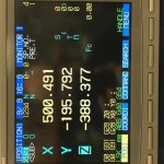
IMG_0173.jpg
 
Last edited:
I figured there would be a semi-auto way of doing this, where I could just jog the Haimer to zero and press a button or two. Am I missing something?

Unless the machine builder customized the U/I to automate setting of fixture offsets, tool offsets, etc. you will be doing something like you have described.

Mori Seiki created functions to simplify fixture and tool offset setting in their implementation of Meldas controls. It's pretty slick and shows what could be done with the control and a builder willing to develop a modded U/I.
 
Typed out a reply and the damn thing was deleted so here goes again.

Stay on the screen in your pic. With your handwheel touch off on your first X position and leave it there making sure that X is the last axis you moved. Then press "1", 1 will now be displayed like this at the bottom #(1) DATA (Your X coordinate is here), and then "INPUT". You will see a highlighted X value in the #1 TLM P.A line. Then move to your opposite X and press "2" and then "INPUT" as you did with 1. Now you should see #2 TPM P.B also have a highlighted X. It might even automatically change the digit after the # at the bottom to 2 automatically after entering 1.

Now if your machine is setup to find the centre of a circle by touching 3 points you need to make sure that you hit "CAN" if 3 is displayed after the # and enter "54" "INPUT". you will see that it calculates the centre of it and inputs it into your G54 X section. Do the same for Y. If you just want to touch off the edge and not the centre then touch off the side of the part and just put in "54" and it will put it into your G54 section. If it gives you a message in the bottom right corner of the screen when you try to input your first x along the lines of "PROGRAM RUNNING" or something like that just hit "RESET" before you start the procedure.

The method I explained is the same for finding the centre of a circle except you need to touch off on 3 points. NEVER EVER touch off 2 points in the same axis after each other when trying to find the centre of a circle, it does not work correctly. You this time you will be using, "1" 'INPUT", "2" "INPUT", "3" "INPUT" in either XYX or YXY order.
If it does not make sense let me know and I can make a short vid for you of me doing it.
 
Oh and on the Z I suppose you have a few options.
I would go to the position screen. Zero off the Haimer. Hit "Z" and then "INPUT" to put z on the screen to 0.0. Then move off the part and move down the distance you need to. Go to the work offset page and make sure that there is a number in the Z position at the bottom. If not click the handwheel one up and one down to get to the position again when you are on that screen. Then enter "54" "INPUT" and be done.

But after my explanation in my post above I am sure that you could figure out a few other ways if you don't want to do it that way.
 
Typed out a reply and the damn thing was deleted so here goes again.

Stay on the screen in your pic. With your handwheel touch off on your first X position and leave it there making sure that X is the last axis you moved. Then press "1", 1 will now be displayed like this at the bottom #(1) DATA (Your X coordinate is here), and then "INPUT". You will see a highlighted X value in the #1 TLM P.A line. Then move to your opposite X and press "2" and then "INPUT" as you did with 1. Now you should see #2 TPM P.B also have a highlighted X. It might even automatically change the digit after the # at the bottom to 2 automatically after entering 1.

Now if your machine is setup to find the centre of a circle by touching 3 points you need to make sure that you hit "CAN" if 3 is displayed after the # and enter "54" "INPUT". you will see that it calculates the centre of it and inputs it into your G54 X section. Do the same for Y. If you just want to touch off the edge and not the centre then touch off the side of the part and just put in "54" and it will put it into your G54 section. If it gives you a message in the bottom right corner of the screen when you try to input your first x along the lines of "PROGRAM RUNNING" or something like that just hit "RESET" before you start the procedure.

The method I explained is the same for finding the centre of a circle except you need to touch off on 3 points. NEVER EVER touch off 2 points in the same axis after each other when trying to find the centre of a circle, it does not work correctly. You this time you will be using, "1" 'INPUT", "2" "INPUT", "3" "INPUT" in either XYX or YXY order.
If it does not make sense let me know and I can make a short vid for you of me doing it.

I've got a MITS controlller on a lathe, so I've never really had to deal with any more than the Z axis to set a work offset, and I usually do that with a tape measure :D

I'm curious, I did you come across this procedure in the programming manual somewhere? I kind of scanned around for it but couldn't really locate what section it would have been under.
I was lucky enough that when the guy commissioned it and saw that all my machines were fanuc he pulled me closer and showed me that and the look ahead options. That is how we figured out that doing the 3 point touch off in a X,X,Y or X,X,X etc etc gave funky results. He touched them off all proudly and I put my finger DTI in to double check and he was faaar off. He tried it twice more with bad results so got on the phone with a guy from his office. First X,Y,X and Y,X,Y landed up being spot on.

I think it might be in the operational manual somewhere but in all honesty I haven't read it much, yeah yeah I was too excited to get it up and running (probably 6 or more years ago), so only really refer to the manuals when I have some problem pop up.
 
.....I'm curious, I did you come across this procedure in the programming manual somewhere? I kind of scanned around for it but couldn't really locate what section it would have been under.

I'm curious too. I don't recall seeing this in my M50 manuals. Never looked though since the Mori interface has it already. The Mori implementation has the setting options assigned to softkeys. You just follow the screen prompts to set the data.

For tool offsets they have a page of U/I parameters that you set to control how you want tool length offsets to be. Lets you pick whether you prefer positive or negative offsets. Height of tool touch block or device and so on. The tool offset setting page includes a toolchange feature. Just click up or down to the tool you want in the spindle, press one softkey and one pushbutton and it changes to the desired tool. No need to switch back and forth between MDI to call a tool and Handle to touch it off.
 
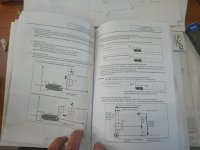
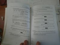
Ok so you guys got me looking into the manual. This is for the 60 Series and it is the Operation Manual. This is the Lathe section and the start of the mill section.
I don't see the 3 point part but I just quickly browsed through it.
 

Attachments

  • 1.jpg
    1.jpg
    87.9 KB · Views: 302
  • 2.jpg
    2.jpg
    87.1 KB · Views: 165
Typed out a reply and the damn thing was deleted so here goes again.

Stay on the screen in your pic. With your handwheel touch off on your first X position and leave it there making sure that X is the last axis you moved. Then press "1", 1 will now be displayed like this at the bottom #(1) DATA (Your X coordinate is here), and then "INPUT". You will see a highlighted X value in the #1 TLM P.A line. Then move to your opposite X and press "2" and then "INPUT" as you did with 1. Now you should see #2 TPM P.B also have a highlighted X. It might even automatically change the digit after the # at the bottom to 2 automatically after entering 1.

Now if your machine is setup to find the centre of a circle by touching 3 points you need to make sure that you hit "CAN" if 3 is displayed after the # and enter "54" "INPUT". you will see that it calculates the centre of it and inputs it into your G54 X section. Do the same for Y. If you just want to touch off the edge and not the centre then touch off the side of the part and just put in "54" and it will put it into your G54 section. If it gives you a message in the bottom right corner of the screen when you try to input your first x along the lines of "PROGRAM RUNNING" or something like that just hit "RESET" before you start the procedure.

The method I explained is the same for finding the centre of a circle except you need to touch off on 3 points. NEVER EVER touch off 2 points in the same axis after each other when trying to find the centre of a circle, it does not work correctly. You this time you will be using, "1" 'INPUT", "2" "INPUT", "3" "INPUT" in either XYX or YXY order.
If it does not make sense let me know and I can make a short vid for you of me doing it.

Boom. I knew it was that easy. Thanks!
 
Last edited:
Oh and on the Z I suppose you have a few options.
I would go to the position screen. Zero off the Haimer. Hit "Z" and then "INPUT" to put z on the screen to 0.0. Then move off the part and move down the distance you need to. Go to the work offset page and make sure that there is a number in the Z position at the bottom. If not click the handwheel one up and one down to get to the position again when you are on that screen. Then enter "54" "INPUT" and be done.

But after my explanation in my post above I am sure that you could figure out a few other ways if you don't want to do it that way.

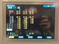
Easy! My only concern is that now my position screen says Z0 when I'm at G54, but the work offset page gives me a different value.

At this point the Haimer is just T1. Obviously I still have to associate T1 H1 with G54.

IMG_0178.jpg

IMG_0179.jpg

IMG_0180.jpg

IMG_0181.jpg
 
Ok so you guys got me looking into the manual. This is for the 60 Series and it is the Operation Manual. This is the Lathe section and the start of the mill section.
I don't see the 3 point part but I just quickly browsed through it.

That's not in my 50 series manual as laid out there, but it might be worth a try anyways, in case it was undocumented in earlier manuals.
 
The actual position screen does not mean much unless you activate G54 or if you want to see where you are relative to your machines home position. If you look your position Z is identical to your G54 offset.

I assume that you hit "Z" "INPUT" to get it to display Z0.0 or did you jog the machine till it read Z0.0? If you are wanting to touch off tools in machine to get their height offsets then touch your haimer off. Get the G54 as you did, then hit "Z" "INPUT" on the position screen. Touch off your next tool and the reading on your position screen is going to be your H value for that tool. If you don't do it this way you would have to add or subtract, in this case -388.377, from each tool to get the difference. I would rather zero out the position screen so you don't land up with fat fingered calculation errors.

There is a way to set the tools by touching them off and going to the offset page and pressing input (you will see if you jogged in Z last there will be a number in the Z positon on the offset screen). These values are relative to a setting somewhere in the control. Do you have a manual? I have the page on it in the operations manual but I do it the way that I described above if setting tools in machine. My values for the automatic offset setting is set somewhere from my spindle nose I think??? But have never used it. I just hit "CAN" if there is some weird number in the offset page and enter the difference of what I am reading in the position screen as explained above.
 
There is a way to set the tools by touching them off and going to the offset page and pressing input (you will see if you jogged in Z last there will be a number in the Z positon on the offset screen). These values are relative to a setting somewhere in the control.

Are the values not relative to machine zero? I've had one instance where we had a fanuc controller factored in g54 into your tool offsets and it was the most irksome thing ever. Took a lot of talking with the service guy to figure out the parameter that needed to be changed.


Back
Top