What's new
What's new

Need G-Code for three axis chamfer path.

Kyle Smith

Stainless
Joined
Apr 25, 2008
Location
Helmer, Indiana, USA
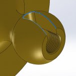
I do not have cam software to generate a path to cut the chamfer highlighted below. If a member can provide the code please send me a PM with your email and I can provide the solid model. It is a native SolidWorks 2019 file, but I can send it in any format that will work for you.

The machine is a 2014 Hass TM-2P mill. For an idea of scale the ball on the part is Ø1.594". The material is Cast C836 Brass. I will be using a 3/8"Ø x 90° included, carbide chamfer tool. The part is mounted on the a-axis with with the ball of the part pointed in the negative X direction, Y0 is the part centerline, X0 is the face opposite the ball. I'm tired of deburring these by hand. :)

Chamfer.JPG
 
What was used to generate the tool paths to create this part minus the chamfer? Some reason the same couldn't be used for the chamfer tool path?
 
Last edited:
I do not have cam software to generate a path to cut the chamfer highlighted below. If a member can provide the code please send me a PM with your email and I can provide the solid model. It is a native SolidWorks 2019 file, but I can send it in any format that will work for you.

The machine is a 2014 Hass TM-2P mill. For an idea of scale the ball on the part is Ø1.594". The material is Cast C836 Brass. I will be using a 3/8"Ø x 90° included, carbide chamfer tool. The part is mounted on the a-axis with with the ball of the part pointed in the negative X direction, Y0 is the part centerline, X0 is the face opposite the ball. I'm tired of deburring these by hand. :)

View attachment 278538

Wouldnt be too hard to fingerbang it.
you just need to make sure you use cut in the xz plane . Done this a bunch of times. that is assuming you have a full 4th axis. if you dont then its trial and error just get it close and and slowly

youll either use a g18 or g17 depending on your direction for the ball part. then the rad in the groove is a rad with x y z moves at the same time.
I dont explain technical things well but its simple stupid.

for a full 4th case has a pretty cool axis flipping code, theres a video on it from back in 2010 when learned how to used it.
 
What was used to generate the tool paths to create this part minus the chamfer? Some reason the same couldn't be used for the chamfer tool path?

The outside profile of the part is a pretty simple 2D shape, just one G03 and one G02, not too bad to fingercam. The chamfer is a bit more complex.
 
Wouldnt be too hard to fingerbang it.
you just need to make sure you use cut in the xz plane . Done this a bunch of times. that is assuming you have a full 4th axis. if you dont then its trial and error just get it close and and slowly

youll either use a g18 or g17 depending on your direction for the ball part. then the rad in the groove is a rad with x y z moves at the same time.
I dont explain technical things well but its simple stupid.

for a full 4th case has a pretty cool axis flipping code, theres a video on it from back in 2010 when learned how to used it.

Maybe, I haven't played around with it. I was hoping for an easy button.
 
Throw a brush in a tool holder, run it up and down the part twice (one M3, one M4) at moderate RPM and feedrate... Boom, broken edge.
 
As has already been said, this is pretty simple. Extract that edge off the work, and if you really have zero CAM, manually enter the start and end point coordinates of the first line, then the end points of all the rest, which will likely be a bunch of small G1 linear moves. Then add a lead in and lead out move so you can also do the whole thing in cutter comp. That way you can dial it in on the machine with either an overall tool height offset or a comp radius offset or both. With your part as shown, this would all be 3 axis simultaneous in the XY plain.

I've done this on 3 axis machines where I'm wanting to chamfer a hole created in the side of an arc. What you have is not much different then that if at all. My ancient CAD will tend to extract this curve off the 3D as a series of lines. If you put the extraction tolerance up high enough you don't end up with hundreds of lines which is not wanted or needed. Keeping it all linear moves also keeps the programming in the standard XY plain. Look ahead will really help with this too.
 
Maybe, I haven't played around with it. I was hoping for an easy button.

you will never learn anything with an "easy button".
like I said its stupid simple.

look up g17 g18 and g19 in the haas workbook. forget that your using a 4th axis. do the 1st line then worry about the second rad. ie take it one step at a time.

once you get those g codes mastered you can do almost anything. There extreamly handy and the haas book does a pretty good job on explainations.
I learned to use these way back in the day with out cad and just a old fanuc book
 
you will never learn anything with an "easy button".
like I said its stupid simple.
So I am looking at this thing and without cam, it's not stupid simple to me. I'd go the TeachmePlease method first, but if not ...

Let's assume he doesn't need an accurate chamfer all around, cuz that's going to be at least four axis simultaneous. Not easy to do by hand. If it's just "break the edge" this is a lot easier.

I'd go for a ball end and try to catch it at a 45 because at least you could keep it tangent to the edge pretty easy. You'd get a little hollow instead of a flat but should be close enough.

The first, srtaight line part is easy, it's straight in one axis and an arc in the other.

BUT the second part, the intersection of a cylinder with a sphere, either he can do a straight line in xz with a simultaneous rotation, or he can do simultaneous xy and xz arcs, not so easy since I am not aware of any controls that can do that ? Does Haas ?

The x-z axis straight move simultaneous with rotary a doesn't sound so easy to figure, and the second way I don't think you can do.


If he doesn't have a $5,000 seat of Mastercam or better, it's a picnic in APT

Define a sphere, three planes and a cylinder

goto/sphere, plane one, plane two
goforward, plane two, to, cylinder
goleft cylinder, to, plane three
goforward, plane three, past, plane one

Four definitions and four statements and Robert Peel is yer uncle .....
 
So I am looking at this thing and without cam, it's not stupid simple to me. I'd go the TeachmePlease method first, but if not ...

Let's assume he doesn't need an accurate chamfer all around, cuz that's going to be at least four axis simultaneous. Not easy to do by hand. If it's just "break the edge" this is a lot easier.

I'd go for a lollipop for that because at least you could keep it tangent to the edge easy.

The first, srtaight line part is easy, it's straight in one axis and an arc in the other.

BUT the second part, the intersection of a cylinder with a sphere, either he can do a straight line in xz with a simultaneous rotation, or he can do simultaneous xy and xz arcs, not so easy since I am not aware of any controls that can do that ? Does Haas ?

The x-z axis straight move simultaneous with rotary a doesn't sound so easy to figure, and the second way I don't think you can do.


If he doesn't have a $5,000 seat of Mastercam or better, it's a picnic in APT

Define a sphere, three planes and a cylinder

goto/sphere, plane one, plane two
goforward, plane two, to, cylinder
goleft cylinder, to, plane three
goforward, plane three, past, plane one

Four definitions and four statements and Robert Peel is yer uncle .....

The problem is, is most of the time people Including my self look at the whole picture and think f-that cant do it with out cam. but if you take each segment/line by its self its simple. just look at start and end points for the 1st line/segment, then go to the next etc etc

there is 3 lines so to speak.
start g17 or g18
1st long line ix a X Z arc, from front of part
then g19 to cancel x z plane
second rad line is a g03 X Y- Z arc rad. to the middle of groove (split into 2 parts). then G03 X Y Z ie to the rnd of left side
then g18 or g17 to start xz plane
third long line is a X Z arc to front of part
then g19 to cancel xz plane

g19 cancels the plane ( you MUST CANCEL the plane, if you dont you will CRASH on a normal move as the g code doesnt stop working after a MOO /M30 M01. its stays there until is cancled and will goto next tool if NOT canceled
I off hand dont remember if its g18 or g17 for the direct he would be cutting. in the x direction I think its g18 for x and g17 for y , you'll need to look it up

Like I said its stupid simple, he has everything he needs as far as dims on his solid works file, just needs to remember to allow for the cutter dia on all 3 sides otherwise he gets a over cut.
so if its a 1" wide slot 1" deep and using a chamfer cutting dia of .050 (z-0.050 tip depth) he would have to program it is a .900 wide groove and .950 in length

g17 and g18 are typically used in surfacing for arcs instead of using segments every mill control I have used can do this, yasnac haas fanuc etc


for haas with a full 4th you use(had to look up the code as I couldnt remember).
G107 CYLINDRICAL MAPPING (X,Y,Z,A,Q,R,)

works fantastic for cutting windows or slots in a round part and keeping your cut outs square to the material. also works on doing text on round parts Rather than running cam to do it and a host of other things.
 
Bejesus...

In the time it would take you to figure this out and hand code it, you could download Fusion, watch 30 minutes of YouTube tutorials, and have this thing modeled, programmed, and cutting.

I love me some history channel as much as the next guy, but whipping out APT is just silly nostalgic circlejerkery.

come on Gkoenig you of all people could fingerbang that out in mins. its takes me about 10 just because I have to find the calculator ;)
 
there is 3 lines so to speak.
start g17 or g18
1st long line ix a X Z arc, from front of part
then g19 to cancel x z plane
I'm with you up to here. This part is easy.

second rad line is a g03 X Y- Z arc rad. to the middle of groove (split into 2 parts). then G03 X Y Z ie to the rnd of left side
This is the part I don't agree with. Are you lazy like me and didn't look at the model carefully ?

That second arc is in TWO planes. It arcs in xy and it's on a sphere so it arcs in xz as well.

I do not know of any control that can do that. Maybe TERA ?

I imagine you can fake it, but that's .... less than wonderful :)

then g18 or g17 to start xz plane
third long line is a X Z arc to front of part
then g19 to cancel xz plane
Again, back to the easy one. Agree with this part, but it's the arcs in two planes -- the radius at the end of the slot plus the radius of the sphere that makes it difficult. Are we going to use cutter comp too ?

Like I said its stupid simple,
If it wasn't on a sphere I'd agree with you. Or I am ignorant and Haas can do arcs in two planes simultaneously. That would be cool.

for haas with a full 4th you use(had to look up the code as I couldnt remember).
G107 CYLINDRICAL MAPPING (X,Y,Z,A,Q,R,)
Possibly, I don't know Haas very much but don't forget, it's on a sphere, not a cylinder. If the Haas can do this particular part easily I'd be impressed. Demo it ?

I love me some history channel as much as the next guy, but whipping out APT is just silly nostalgic circlejerkery.

Quite likely. But I have this weakness for stuff that costs small but works big. Took me all of three minutes to write that program. And it costs nothing. So, thanks much, but between paying Autodesk for some flaky thing in the cloud or running a program written by the brightest minds in the US for free, I'll take door number two.
 
Last edited:
Quite likely. But I have this weakness for stuff that costs small but works big. Took me all of three minutes to write that program. And it costs nothing.

It didn’t take you 3 minutes- it took you 10-20 years. However long it took you to learn APT. Mind you- I think APT was an awesome technology and I have a lot of respect for it. I even get to use its modern equivalent on occasion (NX Sequential Mill), but telling someone to whip out APT for a quick de-burr job is like telling them to whip out their thermodynamics text book to fly from SFO to LAX.
 
Thank you to all for the help. Members Volitan and VTM sent me the code and showed that the cut could not be done with the 3/8"Ø chamfer tool. It interferes with the part as it follows the ball to the center of the part. The cut was made with a 3/16"Ø ball endmill and turned out perfect.

IMG_7636.jpg


you will never learn anything with an "easy button".
like I said its stupid simple.

Yes I know. This is embarrassing to admit, but I am illiterate due to the ease of books on tape. Damn you books on tape.
 
It didn’t take you 3 minutes- it took you 10-20 years. However long it took you to learn APT. Mind you- I think APT was an awesome technology and I have a lot of respect for it. I even get to use its modern equivalent on occasion (NX Sequential Mill), but telling someone to whip out APT for a quick de-burr job is like telling them to whip out their thermodynamics text book to fly from SFO to LAX.

You are using NX and commenting on how long it takes to learn APT ? :D

Let's start with this instance : are we agreed that it is not a simple G02/G03 situation ? If there is a way to program an edge that is simultaneously arced in two planes without using cam, can someone explain ?

(Controls should be powerful enough to do this now, maybe an advance that control people should think about ?)

Kyle, the program that works -- is it a million short lines for the radius at the end of the slot ?


About APT, I don't expect anyone here to use it, all the professionals here are in full-sheep mode. That's fine, but maybe some day someone will do a web search and come across this, maybe a little less closed-minded than the people in this place.

For this part, and other regular-shaped objects, APT is SIMPLE. Drive surface, part surface, check surface.

View attachment 278746

The rest is just a bunch of abbreviations, no worse than g-code.

Seriously, five minutes to program this. Ten if you are a beginner.

Define the sphere - center point and radius. Put a plane at the end of the truncated sphere - three points at that length. Put a plane along one edge of the slot, and a plane at the other edge. Define a cylinder tangent to both edges at the end of the slot - center and diameter.

Geometry done, now motions :

Tell the tool to rapid to the drive surface (edge of slot), with the bottom on the part surface (sphere), and touching the check surface (truncated sphere plane.) Feed along the edge plane to the cylinder. Feed along the cylinder to the other edge plane. Feed along the other edge past the truncated sphere plane.

Done. Simple as apple pie, just as easy as writing g-code.

APT is not God's gift to mankind, the solution to world hunger, and the ultimate computer-aided manufacturing pushbutton "gee whiz, it's all done for me !" tool. But it IS a useful and inexpensive way to solve a lot of programming problems. If people have enough independence to overcome the sheeple mentality "That's so difficult ! That's so old ! that's archaic !" it can be a very efficient way to program a lot of parts.

Did I mention it is free ? Because we, the taxpayers, already paid for it and own it ? In other threads people were going on about how you need to spend $15,000 to do cam. As a small shop, for me that's a no way jose. If they can make F14's and B-1's with this thing, and it's free, that'll do the job for me. I don't mind spending a few hour to learn how it works (how long does it take to "learn" Mastercam ?).

So, you may now return to your regularly scheduled ridicule, but at least the info is out there for people who were not exposed to this years ago.

p.s. Nice looking chamfer :)
 
I'm with you up to here. This part is easy.


This is the part I don't agree with. Are you lazy like me and didn't look at the model carefully ?

That second arc is in TWO planes. It arcs in xy and it's on a sphere so it arcs in xz as well.

I do not know of any control that can do that. Maybe TERA ?

I imagine you can fake it, but that's .... less than wonderful :)


Again, back to the easy one. Agree with this part, but it's the arcs in two planes -- the radius at the end of the slot plus the radius of the sphere that makes it difficult. Are we going to use cutter comp too ?


If it wasn't on a sphere I'd agree with you. Or I am ignorant and Haas can do arcs in two planes simultaneously. That would be cool.


Possibly, I don't know Haas very much but don't forget, it's on a sphere, not a cylinder. If the Haas can do this particular part easily I'd be impressed. Demo it ?

You can adjust the z numbers to make it work close ie close being with in .005, you have to generally use a small 45 degree to small meaning 1/8 dia or smaller.
 
Thank you to all for the help. Members Volitan and VTM sent me the code and showed that the cut could not be done with the 3/8"Ø chamfer tool. It interferes with the part as it follows the ball to the center of the part. The cut was made with a 3/16"Ø ball endmill and turned out perfect.

View attachment 278711


Yes I know. This is embarrassing to admit, but I am illiterate due to the ease of books on tape. Damn you books on tape.
That turned out sweet. but if you dont have cam and cant get help you will need to start playing with it, you would be really surprised how close you can get where a little scotch brite can clean it up.


Back
Top