Hello,
We have some housings we are repairing on an HMC that need bores opened-up. There are three bores on one side and we need to hold the bore-to-bore relationship. I'm looking for help writing a macro to calculate where to move one of the bores after finding the location of another bore to keep the bore-to-bore distances so we don't have to shim the part to get it lined-up. (We only have a B-axis on this HMC so we would need to shim the part for the C-axis unless a macro can be written for this.)
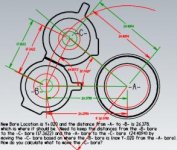
I've attached a drawing showing three bores, -A-, -B- and -C-. I will probe the -A- (X0Y0) and -B- bores. -A- & -B- should be 26.378" from each other in the X-axis and the same location in the Y-axis. If the -B- bore is off location in the Y-axis and the X-axis distance is good, how would I calculate what to move the -C- axis based on my drawing? They are not on the same radius from -A-, so I can't just calculate the angle and use G68 to rotate -C-.
On the drawing I was just messing around and the red dimensions are what the distances are supposed to be and the green was with the Y-axis for the -B- bore +.020 from where it should be, then I just figured the angle and rotated the -C- bore that amount and it didn't work out so well, because they are not on the same radius from -A-.
Anyway, thanks for any help.
Regards,
Paul


