What's new
What's new

New Mastercam user, having some surfacing issues

Machinerer

Cast Iron
Joined
Jun 12, 2009
Location
Clearwater, FL
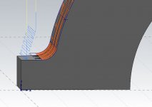
I am an Esprit user, working at a shop now that uses Mastercam. This part is machined with a .500EM, then in the orientation shown in the first picture, a .125R is created with a .500 bull-nose endmill. As you can see in the second picture, because it's a radius, into a radius, it's leaving a little peak. I had fixed it quickly, by drawing out the points and hand-coding a little surfacing routine, walking up the profile a bit to clear the peak, but I'd like to have an accurate MC file, and I'd also like to do it in MC just for my own knowledge. Can anyone steer me in the right direction as to the best way to accomplish this? Hopefully my explanation made sense. Mastercam 2018, by the way.

TOOL ORIENTATION.JPGREST MATERIAL.JPG
 
Looks like you need to surface further up the sides use the tab for the depth of cutting set the upper height and the lower height


Sent from my iPhone using Tapatalk Pro
 
Do you mean the profile is machined in the first orientation except for where the 1/2" EM can't complete the fillet, then the part is flipped 90* to finish the fillet? If so, I would rest-machine the fillet in the first orientation using a smaller necked endmill and depth cuts after the 1/2" EM.

Otherwise you'll need to interpolate the cusp away, which takes lots of passes to get a good surface finish.

Regards.

Mike
 
This was just a regular contour toolpath. I haven't done any surfacing yet in MC so I'm not even sure which toolpath to use, and what to use as chain/geometry. But what you're saying is exactly what I am trying to do. Just walk up the profile a little bit.
 
It looks like to me in the pic the bull endmill needs to come further up the arch to cut the cusp that was left. Are you using a parallel tool paths
If so turn it 90 degrees to machine up the arch


Sent from my iPhone using Tapatalk Pro
 
This was just a regular contour toolpath. I haven't done any surfacing yet in MC so I'm not even sure which toolpath to use, and what to use as chain/geometry. But what you're saying is exactly what I am trying to do. Just walk up the profile a little bit.

To do it this way you would use Flowline or Raster, but neither Flowline nor Raster can do a remachining calculation, so you end up surfacing the entire surface just to trim the little cusp away.

Regards.

Mike
 
Do you mean the profile is machined in the first orientation except for where the 1/2" EM can't complete the fillet, then the part is flipped 90* to finish the fillet? If so, I would rest-machine the fillet in the first orientation using a smaller necked endmill and depth cuts after the 1/2" EM.

Otherwise you'll need to interpolate the cusp away, which takes lots of passes to get a good surface finish.

Regards.

Mike

I wanted to profile the outside with a .25EM. It would have to be 1.625" flute length, but I'm pretty sure I could get a decent finish that way. The "foreman" insists it won't work, and I'm too new here to argue just yet. I may just try it anyways though....
 
I wanted to profile the outside with a .25EM. It would have to be 1.625" flute length, but I'm pretty sure I could get a decent finish that way. The "foreman" insists it won't work, and I'm too new here to argue just yet. I may just try it anyways though....

I would still do the profile first with a 1/2" EM then rest-machine with something smaller.

That is a long reach with a 1/4" EM, but feasible if you use a reduced-shank or neck-relieved stub flute endmill and depth cuts. Low RPM's, and fairly high feed so the cutter can get in and out quickly before harmonics can start up.

Regards.

MIke
 
Depending on the quantity, I would surface both radii. I hate dealing with blend lines from cutting from two orientations (even on multi-axis machines). In this case it would be a pretty simple flow line tool path, starting at the bottom and working up to the top of the radius long wise. The reasons I do it in this direction is it creates the most compact amount of code that yields a smoother toolpath and better finish, and going from bottom to top has less of a tendency to chip weld onto the part.
 
To do it this way you would use Flowline or Raster, but neither Flowline nor Raster can do a remachining calculation, so you end up surfacing the entire surface just to trim the little cusp away.

Regards.

Mike

For either of those operations, I would recommend (to the OP) using depth limits to constrain the toolpath to a little above and little below the Z depth needed to get rid of the bump so they can avoid remachining the whole surface. In Raster, it's under Cut Parameters -> Steep/Shallow -> Use Z Depths. In Flowline, it's on the Finish Flowline Parameters tab, check the Depth Limits box and set the min and max.

Both toolpaths can also be constrained with a containment chain to keep them where needed in X/Y too.
 
Depending on the quantity, I would surface both radii. I hate dealing with blend lines from cutting from two orientations (even on multi-axis machines). In this case it would be a pretty simple flow line tool path, starting at the bottom and working up to the top of the radius long wise. The reasons I do it in this direction is it creates the most compact amount of code that yields a smoother toolpath and better finish, and going from bottom to top has less of a tendency to chip weld onto the part.

This is pretty much exactly why I wanted to surface it, and to avoid any problems from operators. I will give the flowline a try. I tried creating a surface, and using the parallel toolpath based on a suggestion from a coworker, but I didn't seem to have any luck with it.

For either of those operations, I would recommend (to the OP) using depth limits to constrain the toolpath to a little above and little below the Z depth needed to get rid of the bump so they can avoid remachining the whole surface. In Raster, it's under Cut Parameters -> Steep/Shallow -> Use Z Depths. In Flowline, it's on the Finish Flowline Parameters tab, check the Depth Limits box and set the min and max.

Both toolpaths can also be constrained with a containment chain to keep them where needed in X/Y too.

Thank you, i'll give this a try!
 
Got it using raster, a surface created to ignore the counterbores, and a check surface created above the machining surface. Thanks to anyone that replied!!! :cheers:

RASTER.JPG


Back
Top