What's new
What's new

Nikken 5 axis table on Brother TS-2Dn....any idea where the backup batteries are ?

Milacron

Administrator
Staff member
Joined
Dec 15, 2000
Location
SC, USA
Getting low battery alarms for A and B axis.... inside electrical cabinets are two battery enclosures of three AA batteries and two AA batteries. The only other battery I see is one small lithium 3 volt battery on a board. They all check out with close to new voltages on my meter.

So where the heck are the mysterious A and B axis batteries that apparently keep the absolute encoder memory of the Nikken ? They are not INSIDE the Nikken are they ? That would be weird.....OTOH, 6 axis robots have their encoder batteries inside the base of the robot typically so not impossible I suppose.
 
Those 5 batteries should be the only ones. The Nikken table will still use the Sanyo drives / motors that Brother uses. The 3 batteries are for the X,Y,Z, Spindle and the other 2 should be for the additional axis. I just change them all once a year. They just use standard AA alkaline batteries. Just make sure the control is ON when you change them.

The maintenance procedure for those controls for battery changes has a translation error. It says to turn the control off, but actually means to press the E-Stop, not turn the control off. (Our maintenance team learned that one the hard way.)

Stick a USB stick in it and go to <Edit>, <External ....> , then <Maintenance> and do a full backup before you do that. If something goes wrong, you can reload everything (including tool and work offsets) in just a few seconds that way.
 
The set of three AAs in the control cabinet back up all of the servos absolute encoder position data. The set of two AAs back up the NC memory. The set of three should be changed once a year (Control ON) to avoid losing absolute position of all axes. The set of two AAs can last ten years but most shops change them at the same time. The back up battery power for additional axes such as A and B comes from the set of three existing batteries. The servos for the additional axes are daisy chained to the 'basic' X,Y,Z and Magazine servos. The daisy chain cables are the ones that look like USB cables going from servo to servo. When an axis is disconnected from the machine, it will lose its absolute encoder data and that is the alarm you are getting. The axis needs to be reinitialized. Please call Yamazen tech support at 800-882-8558 for help walking you through this.
 
The set of three AAs in the control cabinet back up all of the servos absolute encoder position data. The set of two AAs back up the NC memory. The set of three should be changed once a year (Control ON) to avoid losing absolute position of all axes. The set of two AAs can last ten years but most shops change them at the same time. The back up battery power for additional axes such as A and B comes from the set of three existing batteries. The servos for the additional axes are daisy chained to the 'basic' X,Y,Z and Magazine servos. The daisy chain cables are the ones that look like USB cables going from servo to servo. When an axis is disconnected from the machine, it will lose its absolute encoder data and that is the alarm you are getting. The axis needs to be reinitialized. Please call Yamazen tech support at 800-882-8558 for help walking you through this.
Very interesting. Am I correct that the 3 battery set is wired in series, and therefore should show at least 4.5 volts (more like 4.8 volt with new batteries) on the meter...... and the 2 battery set is wired in parallel and should therefore output the same voltage as 1 battery ? (in this case 1.58 volts)

Re the A and B axis it just occurred to me that the rigger disconnected the Nikken cable connectors for some stupid reason and I'll bet that's why it has lost position memory indeed. Speaking of which, I had no clue which Nikken axis connector went to which receiver connector to the control, as they are not labeled !! I tried both possibilities but got the same errors either way. So that is another mystery....how to know which Nikken cable goes to which control connector ? :confused:

Also, this machine is using a ton of air and I'm mystified where all that air is going as I hear no leaks anywhere. Do Brothers output air into the spindle such that if there is no toolholder in the spindle much of it escapes there ? Another possibility might be the Nikken 5 axis attachment leaking air inside on purpose to keep coolant out ? (had a Hurco 5 axis that was set up that way....leaked air into the trunion ends on purpose for that reason)
 
Stick a USB stick in it and go to <Edit>, <External ....> , then <Maintenance> and do a full backup before you do that. If something goes wrong, you can reload everything (including tool and work offsets) in just a few seconds that way.
Do you know what capacity USB stick is required ?
 
A 10 mb should be plenty. I think there is a max on the B00 control, but don't remember if it is 8 or 16 gb. The files are all ascii files with most being around 2kb in size IIRC. Doesn't take much memory at all. These controls are Linux based, so files are pretty lean. If you have a 1gb stick from a trade show or something that would be enough for many backups.

The cable connectors for the rotaries should have been keyed for orientation. Depending on the set-up, it is most likely the Servo Amp for the tilt axis is a higher amperage (and physically bigger) than the one for the rotary axis. If you open the electrical cabinet, the 4/5 amps will be mounted below the other axis amps, to the right side in the control box. You can follow the cables from the amp to the plugs to help with hooking up the correct cable IF the cables still have a legible label (doubtful on a used machine, but possible).

As for the table and getting rid of the error....

Procedure:

1. Press I/O button
1a. (EDIT) I think you have to press I/O F key then the right arrow, I do it so often to change the write parameter that it is just habit and I can't remember)
2. Press right Arrow key
3. Press "Version"
4. Press "1" then <enter> (Parameter write enable)
5. Press 'I/O Menu" F key
(Takes you back to the very first menu screen of the I/O menu, should see a list of options for the F keys vertically on the screen)
6. Type -9999 and <enter>
7. Bottom right of the screen you will see "Reset Addt'l Axis" (next to last F key)
8. Press that F key
9. Cursor to the first box beside of "A" (or B) axis label depending on how the tilt/rotary is mounted
10. Press "2" <enter> (reset encoder counter)
WAIT until the 2 disappears
11. Move cursor back to that box and press "1" then <enter> (set axis display to 0)

Follow Steps 9-11 for "B" axis (or C axis, depending on how they are on the table)
Press <rst> key (reset)

Note: This just resets the encoders to wherever the table is currently at to be Zero. To properly set up the axis, you would of course tram in the A (or B - tilt) axis and reset the encoder again. - Same for the rotary. You can use the second box over from the A, B or C label to actually tell it a dimension to set the axis to when you do the 1 <enter> thing. i.e. if you tram the tilt axis in at -90° then you would enter -90.000 in the second box over before you did the 1 <enter> of the above procedure. You can also just do a 1 <enter> if you haven't changed motors/encoders and the encoder counts that are displayed match pretty closely.

Or just do as BrotherFrank said and call Yamazen and they can walk you through it at the control in just a couple of minutes.

BrotherFrank: Thanks for the correction I thought the other two were for the additional axis, now I know they are for the control only.
 
Last edited:
The cable connectors for the rotaries should have been keyed for orientation.
If by "keyed" you mean to examine each connection end there should be some hint as to which should connect to which..maybe, I didn't look too close yet. But if by "keyed" you mean one connector flat out will not fit the wrong connector...no such luck...they are identical in size and fit.

There are wrap around stickers on the cables of each receptacle and connector but their numbers appear to reflect connector model numbers ,as the numbers are basically all the same. Seems amazingly lame of whoever did the 5 axis integration to not at least take a Sharpie and scribble some marks to indicate which cable went with which connector. They did differentiate which airline goes where at least, on the Nikken.

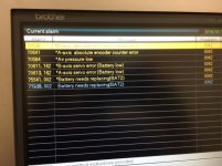
Thanks for the error rid procedure. So it is normal for "replace battery" errors (see below image) to show up when the A and B axis loose position memory..... even when the batteries are not actually low ?

IMG_2776.jpg
 
Yes, you get the battery alarm when an axis motor is disconnected / reconnected to the AMP. (Not sure why that is that way, but it is. - I'm sure the Japanese have a valid reason for doing that, just no idea what that reason is.)

By keyed, I mean that even though the cables are identical in size, the orientation of the key on the connector is in a different radial orientation to the pins on each connector. They shouldn't physically plug up in the wrong connector and the pins line up properly.
 
A 10 mb should be plenty. I think there is a max on the B00 control, but don't remember if it is 8 or 16 gb. The files are all ascii files with most being around 2kb in size IIRC. Doesn't take much memory at all. These controls are Linux based, so files are pretty lean. If you have a 1gb stick from a trade show or something that would be enough for many backups.

The cable connectors for the rotaries should have been keyed for orientation. Depending on the set-up, it is most likely the Servo Amp for the tilt axis is a higher amperage (and physically bigger) than the one for the rotary axis. If you open the electrical cabinet, the 4/5 amps will be mounted below the other axis amps, to the right side in the control box. You can follow the cables from the amp to the plugs to help with hooking up the correct cable IF the cables still have a legible label (doubtful on a used machine, but possible).

As for the table and getting rid of the error....

Procedure:

1. Press I/O button
1a. (EDIT) I think you have to press I/O F key then the right arrow, I do it so often to change the write parameter that it is just habit and I can't remember)
2. Press right Arrow key
3. Press "Version"
4. Press "1" then <enter> (Parameter write enable)
5. Press 'I/O Menu" F key
(Takes you back to the very first menu screen of the I/O menu, should see a list of options for the F keys vertically on the screen)
6. Type -9999 and <enter>
7. Bottom right of the screen you will see "Reset Addt'l Axis" (next to last F key)
8. Press that F key
9. Cursor to the first box beside of "A" (or B) axis label depending on how the tilt/rotary is mounted
10. Press "2" <enter> (reset encoder counter)
WAIT until the 2 disappears
11. Move cursor back to that box and press "1" then <enter> (set axis display to 0)

Follow Steps 9-11 for "B" axis (or C axis, depending on how they are on the table)
Press <rst> key (reset)

Note: This just resets the encoders to wherever the table is currently at to be Zero. To properly set up the axis, you would of course tram in the A (or B - tilt) axis and reset the encoder again. - Same for the rotary. You can use the second box over from the A, B or C label to actually tell it a dimension to set the axis to when you do the 1 <enter> thing. i.e. if you tram the tilt axis in at -90° then you would enter -90.000 in the second box over before you did the 1 <enter> of the above procedure. You can also just do a 1 <enter> if you haven't changed motors/encoders and the encoder counts that are displayed match pretty closely.
A note that I just today got around to running the machine and resetting the A & B axis...and your instructions worked ! :Ithankyou: Very cool machine...never run a Brother before....at least for manual functions more intuitive than Robodrills....I have yet to crack open a manual or call Yamazen and yet have all 5 axis homed, moving about, turret tool changing, rotating, spindle running to full RPM. Have to admit I just guessed at the A & B connections however....the Nikken homes and runs great...but still don't know if A is supposed to be rotary "table" axis or if B is !

One curiosity compared to Robodrill however....in manual mode with door shut....rapid seems only slightly faster than jog speed (with feed over ride knob at 100 percent)...is that how they are supposed to be ? Handwheel mode much faster of course. Wicked fast in go home mode..
 
Yea, it won't jog in rapid anywhere near actual rapid speed even with the door closed in manual mode - which is probably a good thing. You could easily tear up the world manually jogging the table around at actual full rapid speed.

You can set it up either way, depending on how the rotary table is mounted on the machine table. On mine, A is rotary and B is tilt. My tilt center line is aligned with the Y axis and rotary is aligned with the X axis when at -90. You can change it if required. You can look at the axis travel limits in the machine parameters to see which is which originally. I can't remember if they are under switch 1 or switch 2.
 
Note: This just resets the encoders to wherever the table is currently at to be Zero. To properly set up the axis, you would of course tram in the A (or B - tilt) axis and reset the encoder again. - Same for the rotary. You can use the second box over from the A, B or C label to actually tell it a dimension to set the axis to when you do the 1 <enter> thing. i.e. if you tram the tilt axis in at -90° then you would enter -90.000 in the second box over before you did the 1 <enter> of the above procedure. You can also just do a 1 <enter> if you haven't changed motors/encoders and the encoder counts that are displayed match pretty closely.

I have two of these 2012 Brother TS-2Dn machines, but with the second machine I didn't get the original Nikken 5 axis table that was already on there, but instead bought separately from the same company a very similar Nikken 5 axis table set up for similar year Brother D model....the main difference is this Nikken has two rotary fixtures instead of one (that are apparently geared to each other and turn in unison) Same connectors, and I confirmed with Nikken via serial number the table should be completely compatable with the wiring and additional axis drives of this different Brother.

So today I connect it up for the first time and do the error clear procedure and sure enough it works ! The only catch is the B, or tilt axis, will hit a soft limit during forward tilt, way before it should. (assuming 0 degrees with rotary point straight up, it will tilt only about 40 degrees forward...when it should go a little beyond 90 degrees really) So, how do I get the tilt beyond that soft limit to tram it to reset zero to a more favorable home position ? Just enter some guesstamate numbers in the second box over for B and see what happens ?

---------------------------

As an aside, are the dual rotary A axis, 5 axis Nikkens more desirable in general than the single A axis ones ? I guess It depends on the part size, huh ?
 
Nevermind, I think I figured it out...at least for this table...the trick was to set the degrees on the Brother screen at what it was actually at according to the analog scale on the B axis. Now B has the full range of 120 degree motion as it should.

But still curious what folks think about dual rotary A tables on 5 axis attachments, as compared to a single table.
 
2007 brother tc32 bn ft

A 10 mb should be plenty. I think there is a max on the B00 control, but don't remember if it is 8 or 16 gb. The files are all ascii files with most being around 2kb in size IIRC. Doesn't take much memory at all. These controls are Linux based, so files are pretty lean. If you have a 1gb stick from a trade show or something that would be enough for many backups.

The cable connectors for the rotaries should have been keyed for orientation. Depending on the set-up, it is most likely the Servo Amp for the tilt axis is a higher amperage (and physically bigger) than the one for the rotary axis. If you open the electrical cabinet, the 4/5 amps will be mounted below the other axis amps, to the right side in the control box. You can follow the cables from the amp to the plugs to help with hooking up the correct cable IF the cables still have a legible label (doubtful on a used machine, but possible).

As for the table and getting rid of the error....

Procedure:

1. Press I/O button
1a. (EDIT) I think you have to press I/O F key then the right arrow, I do it so often to change the write parameter that it is just habit and I can't remember)
2. Press right Arrow key
3. Press "Version"
4. Press "1" then <enter> (Parameter write enable)
5. Press 'I/O Menu" F key
(Takes you back to the very first menu screen of the I/O menu, should see a list of options for the F keys vertically on the screen)
6. Type -9999 and <enter>
7. Bottom right of the screen you will see "Reset Addt'l Axis" (next to last F key)
8. Press that F key
9. Cursor to the first box beside of "A" (or B) axis label depending on how the tilt/rotary is mounted
10. Press "2" <enter> (reset encoder counter)
WAIT until the 2 disappears
11. Move cursor back to that box and press "1" then <enter> (set axis display to 0)

Follow Steps 9-11 for "B" axis (or C axis, depending on how they are on the table)
Press <rst> key (reset)

Note: This just resets the encoders to wherever the table is currently at to be Zero. To properly set up the axis, you would of course tram in the A (or B - tilt) axis and reset the encoder again. - Same for the rotary. You can use the second box over from the A, B or C label to actually tell it a dimension to set the axis to when you do the 1 <enter> thing. i.e. if you tram the tilt axis in at -90° then you would enter -90.000 in the second box over before you did the 1 <enter> of the above procedure. You can also just do a 1 <enter> if you haven't changed motors/encoders and the encoder counts that are displayed match pretty closely.

Or just do as BrotherFrank said and call Yamazen and they can walk you through it at the control in just a couple of minutes.

BrotherFrank: Thanks for the correction I thought the other two were for the additional axis, now I know they are for the control only.

good day I wonder how the same unit backup installation?
do you have a procedure related to this 2007 brother TC32-BN FT
Will you send me if you have? [email protected]


Back
Top