What's new
What's new

Pivot type joint

sayluv

Plastic
Joined
Nov 14, 2018
Hi-

I make braces and artificial limbs for a living and I have no experience in CNC. I would like to make a smaller adjustable ankle or joint out of aluminum. Here is a picture of what I am trying to fabricate but I would like to make it smaller. It is esentially just to sticks with circles on the ends and they rotate about a center axis. One of them also has holes drilled around the border and a set screw on each end so that we can control the range they rotate about each other.
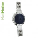
joint.jpg

Range of Motion Joint - MultiMotion™ Contracture Management - Contracture Management & ROM Joints | Allard USA - Support For Better Life!

My question is. If I am able to mill out the two pieces how do I join them in the middle so that they can rotate about the center axis without getting bound up? I think if I used 1/8" alumniun it would likely be strong enough. I could use a chicago screw and washers to hold it togther but I think the joint wouldn't rotate smoothly. Are there parts that I can use for the center post available online?

Any help would be appreciated.

thx, j
 
With the joint being the likely failure point, could you specify the loads and uses of the assembly and its critical-ness? Is this a prototype or in-use part that will be used by a person or is this just a proof of concept or something that won't actually be relied upon? That will determine what you need and can do. Chicago screws are fine for something that goes in your pocket. In real use for someone's ankle, something much more serious is probably needed, but this also looks like this is only one small part of a bigger assembly?
 
Hi-

I make braces and artificial limbs for a living and I have no experience in CNC. I would like to make a smaller adjustable ankle or joint out of aluminum. Here is a picture of what I am trying to fabricate but I would like to make it smaller. It is esentially just to sticks with circles on the ends and they rotate about a center axis. One of them also has holes drilled around the border and a set screw on each end so that we can control the range they rotate about each other.

View attachment 242226

Range of Motion Joint - MultiMotion™ Contracture Management - Contracture Management & ROM Joints | Allard USA - Support For Better Life!

My question is. If I am able to mill out the two pieces how do I join them in the middle so that they can rotate about the center axis without getting bound up? I think if I used 1/8" alumniun it would likely be strong enough. I could use a chicago screw and washers to hold it togther but I think the joint wouldn't rotate smoothly. Are there parts that I can use for the center post available online?

Any help would be appreciated.

thx, j

Funny I am working on something similar-ish / side line for horses... Fetlock not 'Ankle"...

My approach is the exact opposite to not make joints as small as possible make them large as possible with low profile ring (slim/realislim) bearings, and have a large hole through the middle. The idea being that the stresses are not concentrated in on a small area... A Horse weighs 1200 lbs and has reaction forces of the order of 14,000 lbs .


Don't under estimate the torque and leverage you may have and aluminum does not work harden it suffers from metal fatigue from cyclical stresses (internal creep in the metallic structure).


So for the horse thing "Titanium" is the goto + being mindful of the interface between stainless bearings + titanium.


As others have said maybe aluminum is not the best material ?


Also check out flexure assemblies made using nitinol.


Some clue as the extents of envelope allowed and torques and stresses and range of movement could be handy.


All stainless assembly might not be bad... OR if on the aluminum thing you could get the assemblies Hard coat-ed/anodized hard coat then lapped surfaces and use a Teflon washer or bushing or the like might serve well enough but not sure about long term ingress of particles and dirt increasing friction and precipitating failure of the pivot/bearing interface ?


Torque would be length of a man or woman's leg multiplied by weight ? (potentially) 200 lbs x 3 ft = 600 ft pound of torque concentrated into a small area... ?
 
I can't help you with the joint,but why aluminum? Wouldn't titanium or stainless steel be a better choice?

Price and weight and also bendability. We usually need to contour the metal uprights to follow along the side of the brace and aluminum is easy to work with. We do use more rigid materials with heavay adults however.
 
Wrist.jpg

It could be something like a wrist joint for a kiddo that is 1-4 years old, or a very low weight bearing ankle or knee joint for a kid anywhere from 6 months on up. the problem in pediatrics is that very little is manufactured for them since there isnt a lot of profit in it for manufactureres due to low volume. the joint would be riveted of fastened with screws to a brace so part of a larger system in the end, but its use is relativelty straight forward. thanks!
 
Chicago screws are fine for something that goes in your pocket. In real use for someone's ankle, something much more serious is probably needed,

is there anything online that I can purchase that you can point me to for the center screw component. I guess if I use a chicago screw with a washer the two metal uprights wouldnt slide smoothly against each other. I have seen professionally manufactured joints like this that have some type of pivot axel/screw in the middle that is almost like a bearing. thanks
 
Getting a smooth rotation with aluminum can be somewhat difficult. The two mating parts have a tendency to gall when they rub together. This can be overcome a bit with appropriate surface coatings, but I still try to avoid the situation.

Using a Chicago style bolt can work, but you run into a tolerance stack issue. Chicago bolts are generally fairly loose tolerance on both diameter and length. Good for holding two pieces of leather together, not so much a rotating assembly.
Generally when I have a pivot style joint I will use an axle made of 416 or similar. Sometimes I use an e-clip on each side, but in this case I would probably use a axle with a head on it and tap the other end so the end result looked like button headed cap screws on both sides. At the same time, I would probably add a Delrin washer between the two halves to ensure smooth rotation. If I was still concerned about tolerance stack I would add an appropriate tension Belleville washer in the stack, this would provide the appropriate tension at the extremes of the tolerances.

Overall, in volume you are looking at a buck or two in the fastening of the two halves together. Swiss turned parts are cheap once they are running.
 
You could look into small bearings and how to retain them. A good, small, stainless steel bearing would take a lot of load and could be pretty light weight and easy to install into an aluminum assembly.

Example: This is a taper roller bearing, 5/16" wide and fits a 3/8" shaft. Static radial load capacity over 2000lbs.
McMaster-Carr

Our waterjet cutter accidentally used 7075 instead of 5052 on one of our parts that we were bending by hand once, the parts had a big contour (aluminum panel replaced a vehicle window). That thing was like spring steel, very resilient but still light weight, I would take those high end aluminums over the cheap aluminum in an application like this.
 
I think given the lack of much angular velocity it would be well worth looking at Igus plain bearing material. As for joining, you could have your own Chicago style fasteners made on a Swiss which would get the tolerances you need.


Back
Top