What's new
What's new

press fit for small titanium cylindrical components

Joined
Sep 20, 2011
Location
Charlotte, NC, USA
Using medical grade Ti6Al4V, I'm press fitting a circular cylindrical male component 1.5mm (.059") in diameter x 5mm (.197") long. A taper is used at the tip for centering purposes. The mating female side is 2mm (.079") OD, with a corresponding cylindrical blind hole. Here a sketch of a similar cross section:

press fit.jpg

To be clear, the sketch is slightly different OD/ID, but the concept is the same. I'm using a modified fit out of machinery's handbook for tolerances, originally we tried a press fit with interference of 0.004 to 0.020 (.00015"-.0006"). As far as I know an arbor press was used for the press fit. In 3 samples, 1 of them separated under relatively light (think human applied) tensile and torsion forces. I'm trying to eliminate this failure.

Can anyone make any process change suggestions, or design improvements, which would improve this assembly? I am really appreciative of the method of joining process suggestions, e.g, anyone used dry ice/ liquid nitrogen with success? My theory of the first failure was the titanium wasn't ductile enough for the press fit, so this might be a really bad idea:nono: Is a miniature plug weld (laser weld) an option? I'm trying to not distort these miniature parts.
 
Hi Marc:
Are you attempting to make a permanent connection or is this a fixturing setup to allow you to do machining operations on the cap shaped part?
Your choices will depend on the answer to this question.
If the assembly is to be permanent, laser welding is a pretty good option; certainly better than press fitting if you only have a tiny land that's an interference fit as your sketch implies.
However, you could also use an anaerobic adhesive, you could create a snap fit, you could thread the parts together; there are a gazillion ways to go about solving your problem.

With regard to press fits in titanium; they will ALWAYS be a major fight and one of the principal problems is that titanium galls with teriffic enthusiasm, so a press fit that's tight enough to actually do anything is also an invitation to a ruined assembly attempt.
If an interference fit is your method of choice, you will be WAY WAY better off doing a shrink fit protocol rather than a press fit protocol.
Beware of excessive enthusiasm when you heat the female component though; you can wreck the physical properties of the titanium if you get carried away.
It may not matter at all, and the alloy is highly heat tolerant in some senses (it was used for the SR 71 Blackbird after all) but it is responsive to heat treatment, so if the part has been engineered for certain physical properties, you need to check that it will remain OK after it's been in the cooker.
The temperatures and interference allowance will be easy to calculate from information readily available, and titanium is ductile enough to accept significant hoop stress without failure, but you need to be very confident of your numbers especially if this is going to be a part of a medical device.

Last, yes laser welding does distort the part being welded; you can mitigate it with your welding strategy to some extent but you cannot eliminate it.

Cheers

Marcus
Implant Mechanix – Design & Innovation - home
Vancouver Wire EDM -- Wire EDM Machining
Home
 
Marcus raises excellent points, I'll add the following:

1) Can you give us an idea of the use of this assembly? If it's going into a medical application (as implied), does the trapped volume shown introduce any contamination or sterilization issues?

2) How are you measuring the parts? What surface finish is achieved/spec'd? With such a fine tolerance, roughness or error in measurement could easily ruin the design press value.

3) If you decide to do a shrink fit, look into hot air guns for heating the cap, shoot for a target temp of no more than 200C. That will keep the Ti's properties while allowing sufficient expansion for reasonable interference fits.

4) Fixturing will make a huge difference in how successful the process is, don't stint in the design or construction if this is to be a volume part.

If you can give us more information we can try to help a little more.
 
I'm using a modified fit out of machinery's handbook for tolerances, originally we tried a press fit with interference of 0.004 to 0.020 (.00015"-.0006"). As far as I know an arbor press was used for the press fit. In 3 samples, 1 of them separated under relatively light (think human applied) tensile and torsion forces. I'm trying to eliminate this failure.

That's a pretty big range of fit especially at this diameter. Implmex has it right, this stuff likes to gall. I have press fitted some smaller parts than yours, 1mm diameter, and used .01mm interference, but it was quite easy to deform the part during fitting. If we pressed it full depth in one go with a bit of lubrication it was alright but if we stopped for any reason mid-push the part was a goner. Less than .01mm interference and the fit was too weak in our case. We ended up modifying the assembly to use another metal with the titanium.

On your part the wall thickness of the female part is so thin that if you get a good mechanical press fit the outside diameter will have increased (if the female part survives without getting totally distorted/crushed).

If laser welding is indeed possible then I would assemble with a very light interference for location and then weld it up.
 
Thanks for lots of good info. I'll roll up the answers to your questions into one reply.
Are you attempting to make a permanent connection or is this a fixturing setup to allow you to do machining operations on the cap shaped part?
permanent, parts have been finished machined and ready for press fit at this point.

you could also use an anaerobic adhesive, you could create a snap fit, you could thread the parts together; there are a gazillion ways to go about solving your problem.
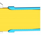
Because of this being a human medical implant, I'm using titanium for lots of reasons but assume I'm not changing the material. Also the use of any adhesives is out, this is a permanent implant. And the gazillion ways, that's why I'm looking to your expertise for the best. A better picture here will help:

press fit big.jpg

These 2 pieces butt together inside the blind hole, the male bottoming out on the female. Third part, shown on the left side, is about 0.45 mm from the lip on the blue part. Is a 0.45 mm gap plenty big for a circumferential laser weld?

If it's going into a medical application (as implied), does the trapped volume shown introduce any contamination or sterilization issues? The trapped volume must be air/liquid tight for sterilization

How are you measuring the parts? What surface finish is achieved/spec'd? With such a fine tolerance, roughness or error in measurement could easily ruin the design press value. Still have to verify QA method, but only in prototype now, surface finish was block tolerance 32 microinches.

Milland your point about shrink fit temp max 200C and fixturing is right on, perhaps heat up the female side chucked up in the lathe spindle, with the male side in the sub-spindle? I know this get a bit complicated without a drawing, but a general fixture idea would be appreciated. An arbor press without guidance isn't going to do it. 8-)

On your part the wall thickness of the female part is so thin that if you get a good mechanical press fit the outside diameter will have increased (if the female part survives without getting totally distorted/crushed).

We are balancing out the female wall thickness with FEA and this is another challenge, the OD is 2.5mm. Good points, Screwmachine. Unfortunately we can't use lubricants that I know of in the medical world. What was your application that the less than .01 mm was too weak?

Here's another option just offered by a watchmaker: knurl or machine an axial spline into the male part only, 1/2 of the length, 2.5 mm. The female bore stays smooth. The spline is on the order of 0.005 high, so the overall diameter of the spline section end up at 1.010mm. Knurling sounds neat, but how to control the dimension, other than finish turn the diameter? What are your thoughts on these ideas?

Right now my solution is a combination of the shrink fit, with proper fixturing, and a circumferential laser weld for the finish. I'd be interested in hearing more of your ideas, and thanks!
 
I cannot imagine a thermal shrink fit working in that size. The cap will cool to match the temperature of the pin faster than you can assemble. Consider that a 1-inch press fit in steel should have about 0.001" interference as a rule of thumb, and that you practically cannot force together such an assembly with 0.003" interference unless the female part yields, you should be looking at a tolerance range of, say, 0.1% of 1.5 mm, which is really tight, unless it is OK for the cap to go plastic and yield. You need to do some engineering to find out how much grip you get if the cap goes plastic (yields), but is still safe from cracking. It seems like laser welding is a good option.
 
That's a pretty big range of fit especially at this diameter. Implmex has it right, this stuff likes to gall. I have press fitted some smaller parts than yours, 1mm diameter, and used .01mm interference, but it was quite easy to deform the part during fitting. If we pressed it full depth in one go with a bit of lubrication it was alright but if we stopped for any reason mid-push the part was a goner. Less than .01mm interference and the fit was too weak in our case. We ended up modifying the assembly to use another metal with the titanium.

On your part the wall thickness of the female part is so thin that if you get a good mechanical press fit the outside diameter will have increased (if the female part survives without getting totally distorted/crushed).

If laser welding is indeed possible then I would assemble with a very light interference for location and then weld it up.


I was gonna say- Wall thickness looks too thin to me to really put a good crush on the male pin for a lot of mechanical grip.
 
You're right Peter. The sketch isn't quite dimensionally accurate as I'm balancing ID/OD right now to make sure the shear from torsion load and tensile loads are equally distributed. The sketch was an early iteration, that wall will need to increase.
 
Hi again Marc:
If you intend to laser weld the assembly, there are some new things to consider:
First, there is now no benefit to making a press fit and dealing with all the processing problems that entails, so I'd consider dumping the press fit completely and aim for a tenth or so of clearance, just enough to put the assembly together without force.

Next, you need to design the weld, and that will change depending on what the functions of the weld need to be.
As an example, you may choose to do a fusion weld if your principal goal is to seal the part and resist low to moderate forces that are oriented mainly along the axis of the assembly.
In such a circumstance you'd aim for zero gap between the parts, and you'd plan to locally thicken the edges of both parts immediately adjacent to the weld so the melt pool can draw from those zones, resulting in an almost perfect preservation of the part diameter if you get the process just right.
If you neglect that, you will get "waisting" or "hourglassing" of the weld zone and only you and your team can tell whether you need to care about it or not.

On the other hand, if this weld will be subjected to significant force as part of its function, you have to achieve deeper weld penetration, and the appropriate weld design for that calls for a bi-bevel at the rim of the weld and the introduction of filler wire.
You may calculate the weld penetration you require in order to meet the engineering objectives, and the depth and flank angles of the weld preparation will be governed by that calculation (along with some other criteria like how much heat you may put into the weld, how well it needs to seal, how much weld distortion you can tolerate, what kind of laser welder you're going to use, etc etc).

Be aware that welding with filler wire GREATLY complicates the weld compared to fusion welding, especially if the application is stringent either for sealing or for strength.
The best way forward with stuff like this is to bite the bitter pill and hire a laser welding engineer with medical device experience; you'll save yourself an immense amount of potential grief.
There are a few of these guys around; the laser welding machine vendors know who's good and who's not, so call them first.

With regard to knurling the male part; I'd try to avoid it.
As Milland points out, dead space in an implanted assembly is a problem on many fronts, and the knurling creates tiny dead spaces all around periphery of the joint.
The most significant is biological: the dead space will become a locus for extracellular fluid and blood plasma which will diffuse into the space and decompose there.
Any bacteremia from any cause (periodontal disease is a common one) will result in bacteria and white blood cells converging on the site and create chronic inflammation of the peri-implant tissues.
Even in the absence of bacteria, a sterile abscess may result if the dead space is big enough and leaky enough.
Cheers

Marcus
Implant Mechanix – Design & Innovation - home
Vancouver Wire EDM -- Wire EDM Machining
Home
 
Marc, a few quick points as Milland and Marcus have this firmly in hand.

I use LN2 quite a bit for stuff like this and it really makes my life easier. At this point in life, I'm fond of things that make it easier...

As mentioned, avoid knurling here. Bad troubles down that road await.

Give up the taper. Believe it or not, it serves only to guide your misalignment perfectly and does nothing to rectify, nor avoid it. If you need something to avoid misalignment, turn ( most likely - grind ) a rebated diameter that is .0025mm - .005mm smaller than your ID being pressed into, for a short length. ( .75mm -ish )

As for the welding, Marcus covered it quite concisely and I cannot add anything of value to it, save to point, nod, and grunt. :)
 
Lots of good thoughts here, but I want to drop back a bit. Why does this need to be an assembly, what's are the components doing? Is the cap a diaphragm, is it enclosing electronics or something? Can you be little more forthcoming with what this does?

It sounded like you're thinking of trying to assemble in the lathe, I can't see how this would work except for early prototyping, as there's no way you could achieve acceptable cleanliness/sterility in that environment. Do you have any engineers with medical product experience working with you?

If you do weld, it might be worthwhile to consider electron beam as well as laser. I think you'd want to be in a vacuum anyway, as even a small amount of trapped gas would risk "popping" the cap off the pin due to heating.
 
I do agree on giving up the taper... However! I would recommend switching it for what I call a pilot... step the nose down .002" (or just a thou or so under your ID so it's a slip fit)- then a 15 degree blend into the press fit. We will often just do the first .080 or .100 or so (about 1/3 to 1/2 the diameter of the pin) of pilot. This is enough to have it assemble very nicely without sacrificing a lot of press fit area.

We make a lot of automotive parts - valve guides and the like- and we ended up putting a feature similar to this on a lot of our parts. It has several advantages over a taper... It lines the part up before you start pressing it into the hole- so the two bores are truely coaxial- rather then possibly crooked... Two, it alleviated a lot of problems we had with broaching the softer of the two parts rather then press fitting.

Going without the pilot requires careful assembly. Stuff has to be square. ;)

RE: Playing with the ID / OD of the two to get enough clamping force- what is the force you are trying to apply to the mating joint? There are calculators online for that, or you can find basic setups some design engineering texts. Since the OD isn't constant though, if it was my part I'd set up an FEA simulation to determine the clamp load after press / shrink fit and also - as mentioned - make sure I wasn't yielding either part.

I would be careful with this- Ti on Ti would also have some very nasty fretting fatigue issues if the joint moves in service.

What about loctite?
 
Marcus, Milland, Zahnrad, Peter, all excellent points. Especially your detail, Marcus, made me appreciate the finer points of laser welding. Your questions: what's are the components doing? this is an implant where the 1st part, the cap (male part) holds the 3rd part to the 2nd (female) part. press fit big.jpg
In this sketch the 3rd part is on the left. The need is for the 1st and 2nd parts to rotate relative to the 3rd. To assemble, the 1st part, the cap, is put through the 3rd part, and press fit into 2nd.

Great guidance on giving up the taper, and reverting to a pilot, Peter and Zahnrad. I had the light bulb moment as you both described it!
Questions about the pilot: How to assemble, given the overall length of all 3 parts is 25 mm? Is an arbor press by hand, with a concentric guide for the OD sufficient? Is it better to guide using the concentricity of a Swiss or manual lathe? Machine powered or by hand?
 
Hi Marc:
As always in these kinds of conversations about processing: it depends.
The first and most obvious question is how many and on what takt time are we talking about.
If the rate limiting steps in the overall process can be improved by assembling on the Swiss, by all means do it that way so long as you don't trash the machine using it as a super expensive servo press.

However, there is an informal process engineering rule that says expensive cutting machines should be cutting as much as possible, especially as the volumes grow.
Time added to the cycle for measuring or assembly steps that don't improve either the takt time or reduce the scrap rate are considered bad machine utilization.

If you have no interference fit and you are relying on the laser weld to hold the assembly together, you may need very little other than the feeding mechanism of the laser welding station, and again depending on volume this can be anything from an operator to a robot to a vibratory feeding system fully automated for lights-out high speed assembly.

However, going back to assembly on the Swiss: if you can produce each part complete on each spindle (especially if you can make them simultaneously) and if you have part orientation on the machine that's worth preserving (like radial orientation), you may wish to capitalize on that advantage regardless what the conventional wisdom says about efficient machine utilization.
You obviously need to find a way to pick up the third part in your assembly and orient it as needed, but that can sometimes be automated easily, and your Swiss then becomes a low/moderate volume production cell that might be most economical overall.
In high volume production, part orientation is one of the big challenges to achieve and can be hellaciously expensive to make reliable; if you can get it for the price of lower machine efficiency, it may be a worthwhile tradeoff.

So there are potentially many ways to skin this cat, and all depends on finding the least expensive way to get good enough assemblies in the best time overall.
Without knowing all of what it is and what it does, we cannot really help much beyond these kinds of general statements.
Cheers

Marcus
www.implant-mechanix.com
www.vancouverwireedm.com
www.clarusmicrotech.com
 
Well, if it was me... I wouldn't bother making it much of a press fit at all (if any) if I was also going to laser weld it. Depending on the concentricity requirements, a slip fit- especially a looser one- is so much cheaper / less hassle to machine...

The smaller it gets the tighter the tolerance for the press fits. Seems a waste to me if you're gonna weld it anyways.

RE: Press fit assembly: we use an arbor press for some jobs, they are fast... Others- we use a hydraulic press. Also possible to retrofit a pneumatic cylinder for very fast work- but be careful how you set that up. Gonna move fast. Depending on quantity, I'd still be looking at using some heat to at least ease it- Titanium just likes to gall so readily. If you're going to go straight up, I'd probably reach for some moly lube to hopefully help prevent galling.

The important thing is to make sure that the press fit you designed in is actually there when you assemble it. If the hole gets broached out, or shredded- you could have failures.

If this is some sort of medical or other high risk application, I'd get an engineer to look at that press fit, the loads associated with it, and sign off on the thing.
 
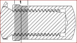
Thanks to all this excellent input this problem was solved. Like many engineering problems, after looking at lots of complicated solutions I substituted a simpler one. Instead of a press fit, I used an M2 x 0.25 thread, locking it with a through penetrating circumferential laser weld. Check the image here:

laser weld assembly.JPG

Key was a lot finite element analysis to balance the failure loads of the male/female threaded components. Physical prototypes under benchtop tests exceeded the predicted results. That doesn't happen often.:cheers:


Back
Top