What's new
What's new

Question on hand written G41 cutter compensation

sendithard

Plastic
Joined
May 18, 2021
I'm needing to write a simple contour path leaving .010" stock then a finishing pass for this class I'm in. I understand how to write the G41 cutter comp and how to properly turn it on and off with a G01 pre-move.

Below is a picture of the part. I read somewhere instead of entering D01 and pulling from the T01 diamter(radius) offset you can instead manually enter a P0.25 to reflect the radius of a 1/2" end mill.

This got me thinking if you can avoid doing trig to get the .010" offset outline of the part by entering in that additional .010" into the P value. So if I enter a P value of 0.26 will this effectively push the 1/2" cutter that extra .010" away from the part so I am left with that amount of stock? If this is the case, it would make handling the handwritten gcode much easier at non-perpendicular corners.

And just so I understand how the controller is working...to get the proper cutter placement in the 2nd photo...is it doing the necessary math to push this cutter tangent to the next line created by the next G01 location by means of some type of lookahead?

My next question relates to the above but I'm wondering if I instruct the cutter to round the corner of the part at 2,2 as seen in the 3rd photo will the G41 then do the proper round when I again use the P0.26 as seen in the 4th photo?

Thanks.

part1.JPGpart2.JPGpart3.JPGpart4.JPG
 
I have not seen the P-method on a Fanuc. Maybe, it is available on some controls.

The outside corner is always correctly made by the control. The extra motion at the corner, which is automatically introduced by the control, is control-dependent. Fanuc uses overtravel method rather than rotation at the corner.

To leave an allowance after machining with radius compensation, a simple way can be to specify a slightly larger radius value in the offset table.
 
I have not seen the P-method on a Fanuc. Maybe, it is available on some controls.

To leave an allowance after machining with radius compensation, a simple way can be to specify a slightly larger radius value in the offset table.

That was my initial thought exactly, but I'm assuming you need a tool change to a new finishing tool with the proper diam enter in the offset. If I'm able to use the P-word instead of D it seems like you could rather quickly program a ton of roughing passes if you wanted to take small radial cuts at a higher speed. I will be using a Mitsubishi M-80 controller.
 
I should make that part with saw and file. Sorry, avowed CNC hater here

G41 just exchanges tool center with tool tangent point. The control adds a circular motion interpolated from tool radius and corner angle. It’s not a circle line but a stepped going around, the step width dependent on F.
 
On Siemens controls you can add an optional allowance on the programmed contour with OFFN=<value> together with G41/G42. I have not seen this option on Fanuc controls.

On the corner rounding: According to my Fanuc 30i manual, "preserve vector" or "corner circular interpolation" behavior for tool radius compensation is selectable by G-code.
 
...... Fanuc uses overtravel method rather than rotation at the corner.
.
Is this true of all Fanuc controls to date?
Would seem like a lot of wasted time cutting air on a 160 degree corner not to mention the servo jerk.
The big plus, sharp corner and enough time to get back up to speed before tool contact with material.
The big minus, time, servo error and lord forbid if it a groove or slot as the outside edge is....
I've seen people say "That's a Fanuc corner".
Bob
 
Is this true of all Fanuc controls to date?
Would seem like a lot of wasted time cutting air on a 160 degree corner not to mention the servo jerk…..

Fanuc at least as far back as the 15 series from the late 80s allows the use of G39 to roll the tool around a vertex.

This really only affects programs that follow the part profile and use full radius comp as opposed to a program that follows tool centerline and little to no comp in offset.

Since most tool centerline programs are CAM generated, the CAM software would be responsible for rolling the tool around a corner.
 
Thanks for the replies. I'm about to write the simple finishing pass for this gcode with G41 comp.

You can see the below pic. I understand how these controllers can lookahead and go beyond a surface to catch the tangency of the next surface....BUT can these controllers do this when the next surface lookahead is a half circle seen below? Something inside me just doesn't feel right letting the damn cutter comp take a stab at this.

From what's been said I would just forget about manually finger typing those vertexes roll arounds and just let the controller handle them however it does.

As I approach this half circle on the bottom pass I'm imagining this would work...The software just needs to know it must go a full radius past the vertex prior to beginning the arc.

G01 X3 Y0;
G03 X1 Y0 I-1.0;
G01 X0 Y0;
corner.JPG
 
I'm needing to write a simple contour path leaving .010" stock then a finishing pass for this class I'm in. I understand how to write the G41 cutter comp and how to properly turn it on and off with a G01 pre-move.

Below is a picture of the part. I read somewhere instead of entering D01 and pulling from the T01 diamter(radius) offset you can instead manually enter a P0.25 to reflect the radius of a 1/2" end mill.

This got me thinking if you can avoid doing trig to get the .010" offset outline of the part by entering in that additional .010" into the P value. So if I enter a P value of 0.26 will this effectively push the 1/2" cutter that extra .010" away from the part so I am left with that amount of stock? If this is the case, it would make handling the handwritten gcode much easier at non-perpendicular corners.

And just so I understand how the controller is working...to get the proper cutter placement in the 2nd photo...is it doing the necessary math to push this cutter tangent to the next line created by the next G01 location by means of some type of lookahead?

My next question relates to the above but I'm wondering if I instruct the cutter to round the corner of the part at 2,2 as seen in the 3rd photo will the G41 then do the proper round when I again use the P0.26 as seen in the 4th photo?

Thanks.
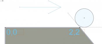
View attachment 331703View attachment 331704View attachment 331705View attachment 331706

At least for me, it is fairly common to add finishing allowance to the tool offset via macro if I am using cutter compensation. You only need to write the path once and you let the control mostly do the math it is so good at. It is a time saver when programming.
 
…...BUT can these controllers do this when the next surface lookahead is a half circle seen below? Something inside me just doesn't feel right letting the damn cutter comp take a stab at this……..

……As I approach this half circle on the bottom pass I'm imagining this would work...The software just needs to know it must go a full radius past the vertex prior to beginning the arc.

G01 X3 Y0;
G03 X1 Y0 I-1.0;
G01 X0 Y0;
View attachment 331741

Yes, the control can figure out how to comp the path for the contour shown.
 
Fanuc at least as far back as the 15 series from the late 80s allows the use of G39 to roll the tool around a vertex.

The older controls rolled around a corner. Newer ones use linear moves.

On the corner rounding: According to my Fanuc 30i manual, "preserve vector" or "corner circular interpolation" behavior for tool radius compensation is selectable by G-code.

Someone (else) better tell angelw. I'm kinda tired of his ignorance.
 
Someone (else) better tell angelw. I'm kinda tired of his ignorance.

Pretty tough to say angelw is ignorant. He’s one of the most knowledgeable and helpful members of this forum.

In the Fanuc case, squaring off comped corners is the default behavior. G39 is a one-shot code and must be included on every move that one wants to round the vertex.

Nobody knows everything about each particular control. Years ago I was teaching a programming class for some brand/model control I don’t recall now. Was starting to go over drilling and tapping canned cycles. Told the class to hold on a second because I wanted to take a peek in the manual to confirm the function of one of the addresses. Some wag there spoke out saying something like “hey, you’re the teacher, aren’t you supposed to know that”. Kinda rubbed me wrong so I responded by listing off all the makes and models of controls I was expected to know how to program including mill and lathe versions. Then said something like “and you’re just trying to learn how to program one”. It shut him up.
 
Pretty tough to say angelw is ignorant. He’s one of the most knowledgeable and helpful members of this forum.
About Fanuc, but Fanuc ain't the sum total of controls in the universe.

btw, I find a discussion of general principles more helpful than a cookbook answer, but maybe I'm weird.

Nobody knows everything about each particular control.
My point exactly. Which is why people should not say things like "You don't know shit, this is how it works" when what they know is how it works for Fanuc. (And apparently, not even all of Fanuc.)

Years ago I was teaching a programming class for some brand/model control I don’t recall now. Was starting to go over drilling and tapping canned cycles. Told the class to hold on a second because I wanted to take a peek in the manual to confirm the function of one of the addresses. Some wag there spoke out saying something like “hey, you’re the teacher, aren’t you supposed to know that”. Kinda rubbed me wrong so I responded by listing off all the makes and models of controls I was expected to know how to program including mill and lathe versions.
Which is why Fanuc pisses me off, since there are standards, but Fanuc does not follow them.

Fanuc is reliable and they support older models but otherwise, they are a shoddy product. There were many US built controls that were more advanced, more intelligent, more capable, nicer to use than Fanuc. Why people adore that garbage then turn around and act all patriotic, amazes me.

Someone has his panties in a bunch. Please do not go this way.
When people make adamant statements that are false, it pisses me off. To say "Fanuc 18 does this ..." is fine. To say "CNC controls do this ..." is not fine. It's misinformation, aka a lie. Despite many examples to the contrary in today's world, truth counts, ya know ? Or at least it should.
 
When people make adamant statements that are false, it pisses me off. To say "Fanuc 18 does this ..." is fine. To say "CNC controls do this ..." is not fine. It's misinformation, aka a lie. Despite many examples to the contrary in today's world, truth counts, ya know ? Or at least it should.

Like when you say that Cutter Radius Comp can be done without Look Ahead Blocks. Try looking in the mirror.

That's not possible with any control, let alone any specific control.
 
Is this true of all Fanuc controls to date?
Would seem like a lot of wasted time cutting air on a 160 degree corner not to mention the servo jerk.
The big plus, sharp corner and enough time to get back up to speed before tool contact with material.
The big minus, time, servo error and lord forbid if it a groove or slot as the outside edge is....
I've seen people say "That's a Fanuc corner".
Bob

If the required overtravel is more than the radius of the tool, the path is chamfered, i.e., one additional linear move is introduced.


Back
Top