What's new
What's new

Radial turret alignment using grid shift. Possible?

13engines

Stainless
Joined
Jun 30, 2015
Location
Saint Paul, MN
2000 Mori Seiki SL200-SMC 12 station all live turret. Fanuc 18iTA

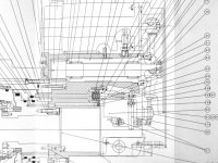
I've been doing some alignment checking on my lathe and am finding that I'd like to rotate the turret to bring the Z axis tools into better position by 2 or 3 thou. I get less then a thou change in 9.5" of X travel measuring on a large precision parallel clamped in a tool space, but can't seem to set a bore in the Z axis to an X position that makes the Y position play along.

After staring at the parts book drawing I'm beginning to think that the way you adjust the turret rotation is by changing the grid shift, and not loosening bolts and pulling pins. The turret is driven by an absolute encoder servo motor driving a spur gear. The turret rotates without lateral movement on it's axis. I can hear and sense the hydraulic un-clamping and clamping of the turret. I haven't looked but am pretty sure there is a grid set for this servo as all the servo drives have battery backup going.

Anyone have experience with this? Am I on the right track?

Thanks for listening.
Dave
 
No lateral movement in my mind would eliminate two cervical coupling meshing to lock it down but I'd think there'd be something more than hydraulic pull back pressure holding it in place? There almost has to be some kind of locking mechanism holding it to casting side itself.

What you're saying sounds like it would align the rotation with the rest of the world but how is it being clamped down be my question? Seems it'd have to be rotated also? Without seeing the drawing this is all speculation of course.

Brent
 
I'm sure that it has a gear type coupling of some sort.
The shifting of the encoder value is just to get it to land in the right spot before clamping.
The gear type coupling will doo the final location upon clamping.


-------------------

Think Snow Eh!
Ox
 
I'm sure that it has a gear type coupling of some sort.
The shifting of the encoder value is just to get it to land in the right spot before clamping.
The gear type coupling will do the final location upon clamping.

Thank you for the responses. I'm beginning to think you're right. Even though there is no perceptible lateral movement during tool change, there is a pin that retracts and re-homes and has two prox sensors that are likely letting the control know what state it's in. As many of you may know, these cutaway drawings can be very deceptive about what you're looking at until you've seen the parts in the flesh. I'll take an exploded view any day though you'll see those more in an assembly manual.

This is a slant bed lathe, which I realize I should have mentioned earlier. I've come to think that rotating the turret could alter or fix that thou movement in X mentioned earlier, and at the same time mess with what I'm calling the Y component of a Z axis bore measurement. Am I correct that on a slant bed, errors in X and Y are corrected by radial turret adjustment? If X and Y are corrected separately, how is that done? (The basic concept or avenue of work should suffice.)

I've included some drawings. The standard drawings show the tool change parts. The one without the part number balloons is one showing only the parts changed for the MC or live turret type. I've included it because it's a little less busy. I've also included one live turret picture. There's a ton going on in there.

Until I can get a Z axis bore that I can believe in I'm likely not going to get too drastic with this. Right now all my Z axis bore holders are used, have many set screw holes that have to be dodged, and I don't like that idea of setting critical physical machine components with something that has such a great chance of introducing errors of it's own like a well used boring bar holder. Even if you clamp a perfectly ground bar into one of these holders, it's being held in with setscrews like an end mill holder, which are not the best for trying to check Y location after setting X, as those set screws completely mess with the Y position.

What do people use? Truth be told, these are the holders that will be used to make stuff, so do you just dial each one in the best you can and call it good? Or is it only after noticing a trend that you start adjusting physical machine parts?

Think I'll hit up Mori for a set of alignment instructions. Doubt they're going to have something they'll give away but it's worth a try. It might be worth it to have a service person come out and do it once. I could take what I see done there and use it for the duration. There are some taper issues too that could be looked at.

Thanks for any help.

Dave
 

Attachments

  • SL200 MC Type.jpg
    SL200 MC Type.jpg
    96 KB · Views: 287
  • SL200 Standard PN.jpg
    SL200 Standard PN.jpg
    99 KB · Views: 111
  • SL200 Standard_3.jpg
    SL200 Standard_3.jpg
    92.1 KB · Views: 344
  • SL200 Standard_2.jpg
    SL200 Standard_2.jpg
    98.3 KB · Views: 167
  • SL200 Standard.jpg
    SL200 Standard.jpg
    94.1 KB · Views: 246
if your Y is off the only thing you could really do is new shim plates to bring the turret to center. but how far off is the Y when you sweep it?
 
13:

If your other tools are fine - worrying about a boring bar woulf be about the last tool in my concern - unless you were possibly facing the bottom of a bore and was leaving a tit, but even the - you could prolly tweak it?

I just chuck up small bars in a collet, and you can twist them 7 ways from Sunday to get them like you want that way.
I would think that the set screw flats could easilly push a bar up or down while tightening the amount that you are talking about.

And I Shirley can't see an 1.25 bar being off (or on) by .003 even remotely possible to determine (or matter).

Are you having troubles with sumpthing - or just lookin' fer trouble?


--------------------

Think Snow Eh!
Ox
 
if your Y is off the only thing you could really do is new shim plates to bring the turret to center. but how far off is the Y when you sweep it?

Casanova,
Well two to three-ish. So jack the whole axis up with shims? I've got to verify things a lot better before I get into that idea.(Like my test tools as stated.) But it is a way.

13:If your other tools are fine - worrying about a boring bar woulf be about the last tool in my concern - unless you were possibly facing the bottom of a bore and was leaving a tit, but even the - you could prolly tweak it?

I just chuck up small bars in a collet, and you can twist them 7 ways from Sunday to get them like you want that way.
I would think that the set screw flats could easilly push a bar up or down while tightening the amount that you are talking about.

And I Shirley can't see an 1.25 bar being off (or on) by .003 even remotely possible to determine (or matter).

Are you having troubles with sumpthing - or just lookin' fer trouble?

Ox,
I guess I steered things wrong or am misunderstood. I'm not concerned about boring bars per say, but regular drills held in bar holders with bushings. Or cylindrical shank ER adapters holding drills or chamfers. Insert drills in bar holders with Komet ABS50 adapter shanks in them. Also live drills on Z axis, and like that. A boring holder was simply what I had used to make some first measurements.

Reading through these answers gives me avenues on how to deal with Y problems on a slant bed lathe without a Y axis.

1) Although not ideal, use the opposing set screws on the boring holders to work out the error in Y. After all the tweaking, it will still leave some uncertainty about how parallel to the machine spindle the drill is pointing. Especially with a drill mounted and not a test shaft.

2) Correcting Y error must be the use for those set screws you see on the underside of the live tool holders on this BMT turret. I haven't played with those yet but fixing Y error might be at least part of why they're there.

3) Use a Z axis ER live tool block as a potentially higher precision hole to indicate to. Measure TIR of the rotating live tool taper to verify that it hasn't gone south. Load a ground bar in a collet and verify axis alignment, then use that taper to set X and the set screw on the bottom to handle Y. And to think this machine already takes forever to set up. Sheesh!

Not looking for trouble Ox, just that this is a new machine to me. A CNC multi axis live lathe is also new to me, and so much of it's setup and function doesn't seem to care at all that I have a lengthy background in CNC milling and machine tool rebuilding under my belt. Years on a manual lathe too. I've run into some other issues with it, including the taper turning I spoke of, so as usual with me I'm giving it the once over. It's a sickness I've had for many years. Nothing I can do about it now.

Thanks all. Still curious about the actual turret rotation adjustment if anybody figures it out.

Dave
 
.....Still curious about the actual turret rotation adjustment if anybody figures it out.

The final turret index position is determined by the curvic coupling alignment. The servo driven rotation can have a tweak to the grid shift to more closely align the coupling before engagement, but that won't affect the final alignment.
 
The final turret index position is determined by the curvic coupling alignment. The servo driven rotation can have a tweak to the grid shift to more closely align the coupling before engagement, but that won't affect the final alignment.

What he said ^
Perhaps pull the taper pins, maybe they are bent...

Has the machine ever been crashed?
 
Prolly #26 through #31 on page 3.

3 piece Hirth.

I think you're right again. Even Mori, who has gotten lame over the years in there part name call-outs calls them all "coupling". Works for me.

In the live tool drawing I'm seeing how the entire front end comes off as one assembly. Either leaving the bevel gear exposed or taking it with it and drawing the spline shaft out of the translating, belt driven live tool drive shaft. Still I don't believe any of this has to come off to adjust the turret.

There are those deeply set bolts under plugs. (#5 near the top)From the outside they look like they're what bolts the tool holder body on. Loosen those and then what?

Unless someone describes the process or Mori gives me the relevant info, I think if I do decide this thing definitely has problems, I'm going to pay the price and have someone come in and do it the first time. I can get all the sheet metal and stuff out of the way which will save a ton of time and money.

The last thing I want to do is break something that isn't broken but maybe only has a mild cold.


Dave
 
Does your turret have the stick tool holder pockets built in?
If so - have you swept those while jogging X?

.003 is next to nothing IMO.
Is that TIR?

Check repeatability.
Index it away and come back and check aggin.
Now index it away the other way and come back and check aggin.
(checking for worn couplings)

Now, take your boring bar holder off and remount it.
Doo you git the same every time?

Have you checked all the holders in every position?
Doo you git the same .003 in all pockets every time?

I don't know your machine config, but live holders are wildcards, and .003 on your turret likely will have no relivence to your live tool being right as soon as you bolt (?) it on.


-------------------

Think Snow Eh!
Ox
 
Does your turret have the stick tool holder pockets built in?
If so - have you swept those while jogging X?

.003 is next to nothing IMO.
Is that TIR?

Check repeatability.
Index it away and come back and check aggin.
Now index it away the other way and come back and check aggin.
(checking for worn couplings)

Now, take your boring bar holder off and remount it.
Doo you git the same every time?

Have you checked all the holders in every position?
Doo you git the same .003 in all pockets every time?

I don't know your machine config, but live holders are wildcards, and .003 on your turret likely will have no relivence to your live tool being right as soon as you bolt (?) it on.

Yes the one new picture shows a precision parallel I had properly held in the tool space. Of course I had it tipped to the active position. I got nine tenths over the entire machine travel in X measuring on top. Don't recall what I had measuring the face but it was not shocking or I'd remember it.

I have yet to try all these things you've suggested in a protracted and orderly manner. I got excited originally because I thought how easy it was going to be to grid shift away my perceived problems. Not so I guess.

Here are some pics of the turret and machine in general. I included a couple I took during the initial once over of the machine when I got it. My sickness as I said. Figured not too many people get to see a CNC lathe with all the sheet metal off.

Thanks everyone for the help. I have some measuring to do. Hope I don't have to remove all the sheet metal again.

Dave
 

Attachments

  • IMG_2094.jpg
    IMG_2094.jpg
    90.7 KB · Views: 106
  • IMG_2098.jpg
    IMG_2098.jpg
    92.7 KB · Views: 128
  • IMG_2100.jpg
    IMG_2100.jpg
    94.5 KB · Views: 97
  • IMG_2108.jpg
    IMG_2108.jpg
    86.9 KB · Views: 110
  • IMG_2249.jpg
    IMG_2249.jpg
    90.1 KB · Views: 330
Unless you are doing some pretty tricky micro drilling, and some very accurate Face design---.003" LMAO. Have a beer or 6.

R


Back
Top