What's new
What's new

Ran into a problem setting a groove tool

jpkulu

Plastic
Joined
Jul 31, 2018
I was running a lathe recently and ran into a problem setting a tool. Normally I've changed out boring bars and set the X and Z but never really have to mess with the R (radius) and T (tool position) values for cutter comps because the boring bars I run all face the same direction and we rarely change tool nose radi.

Long story short, I had to take a boring bar out and put in another one for an ID groove. The groove insert is a full radius insert .188" in width. I taught the tool in Z and X as I've done many times before with other tools, and I then changed the R value to .094, and the T value to 6 (It was 2 for our previous boring bar).

A previous tool did a face pass, backed up .100, and homed out before I changed this boring bar. I then went to run the groove tool and it came close to running into the part. The path it was going to take in X should have been exactly .100 above the face that was cut previously, and the value on the coordinate system said it was the same place in Z as was the other tool when it traveled that path backing away from the part. For some reason the bottom of the groove tool was about even with the face of the part.

Since the width is .188, half of which is .094 (almost the .100 gap that should have been there), the only thing I can think of is that when I changed the T value to 6 from 2, and the radius comp from .047 to .094, it must have factored in the center point of the width of the groove tool as being a compensated value for Z and didn't keep my initial Z value that I taught the tool at. That still doesn't make sense to be though because I've never had this problem with regular inserts like cnmg 432s which also have tool directions and radi.

Does anyone have any insight on what happened?
 
Unfortunately I don't have all of it. I'm just an operator, and most of the code is buried in macros and variables.

In part, it's


G20

(macro callup)
G0 G28 U0. W0.;
G04 X1.;
T[FIX[#4120/100]*100];
G0 G20 G40 G99;
G50 X43.522 Z26.492 s400;
M99


G0 T0606;
M8;
G97 S30 M03;
G0 G54 X26.7 Z9.1;
G50 S200;
G96 S200;
X15.0 (problem happened while rapiding to here)
Z5.0
G1.......
 
When you reset your X and Z offset did you put it in T2 offset?
Then edited to T0606 and it calls up old offset left in tool 6?
 
When you touched off your Z with the groove tool did you base it on the edge or the center of the groove tool? Might need to go touch on your Z0 with the face of the groove tool and tell it that Z0 is actually -.094 for that tool.
 
Long story short, I had to take a boring bar out and put in another one for an ID groove. The groove insert is a full radius insert .188" in width. I taught the tool in Z and X as I've done many times before with other tools, and I then changed the R value to .094, and the T value to 6 (It was 2 for our previous boring bar).
Hello jpkulu,
When you say "I taught the tool in Z and X as I've done many times before with other tools", if that means that you set the tool in Z on the Leading edge of the Insert, there's your problem right there. When determining the Imaginary Tool Type Number, you must consider the setting of the tool. If the Grooving Tool was set in the same manner as a standard Boring Bar would be set (Leading Edge of the Insert in Z and the point on the Insert closest to the centre line of the machine), then the Tool Type will be 2, not 6. To set as a Tool Type 6, Z would have to be set to the centre of the Tool Nose Radius in the Z axis and at the point on the Insert closest to the centre line of the machine in X.

Regards,

Bill
 
z.jpgx.jpg


I set them like this. So this is still considered a tool two position? That still confuses me because If I incorrectly taught it this way as a tool six I would think that it would have made the tool higher not lower.
 
View attachment 237777View attachment 237778


I set them like this. So this is still considered a tool two position?
Hello jpkulu,
It will definitely be a Tool Type 2. You have set this tool in the same manner as you would a standard Boring Bar; accordingly, why would a different Tool Type number be used than the number you would normally use with a Boring Bar?

With your reference to Higher and Lower, is this a Vertical Lathe? For clarity, it would be better to specify any error in terms of Positive and Negative position.

That still confuses me because If I incorrectly taught it this way as a tool six I would think that it would have made the tool higher not lower.
That is the reason for suggesting you Post a copy of the program you're having issues with. The Tool Path Profile being cut and where the TNR Comp is applied has a lot to do with how the tool is positioned. The program snippet posted in Post #3 shows that you're using both G50 and G54 to set the Workpiece Coordinate System and nowhere is it shown TNR Comp being applied. However, if TNR Comp is already applied prior to the "G0 G54 X26.7 Z9.1" Block, then the tool would offset to the Z Minus direction (Lower in your terms) when the following Coordinate Blocks are considered by the control.

G0 G54 X26.7 Z9.1;
G50 S200;
G96 S200;
X15.0 (problem happened while rapiding to here)
Z5.0

I don't quite get the purpose of the following Macro Program, in particular the T[FIX[#4120/100]*100] Block.

G0 G28 U0. W0.;
G04 X1.;
T[FIX[#4120/100]*100];
G0 G20 G40 G99;
G50 X43.522 Z26.492 s400;
M99

If the last tool call was T0303, #4120 would be 303 and therefore T[FIX[#4120/100]*100] would equate to T300. I assume this is to ensure that the previous tool offset is cancelled before the G50 (Work Coordinate System Set) is executed. However, "G0 G28 U0. W0." would have placed the X and Z axes slides at the Reference Return Position.


Regards,

Bill
 
Last edited:
Capture.jpg Untitled.jpgI had to change the tool type previously at another shop, but it's been a few years, and I now can't remember why. I think I screwed up in doing it, but since I have looked over the program, radius comp isn't even turned on.

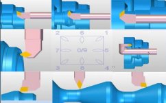
Yes, it's a vertical lathe. The picture is why I thought it was a tool 6 position. That's the direction that the tool is facing. I believed, maybe falsely, that the tool position was telling it that the radius, as specified in the R column (.094 in my case), is present between the 6 and 12 o'clock position for t6, and between 430 and 1030 for tool 2 position.

If radius comp isn't even turned on with a g41 or 42, wouldn't this be ignored by the program offset anyway?

I would also think that if it was not ignored, that it would be more positive in Z rather than negative, because the way I'm picturing it in my mind is that the program would think that I taught the tool at the tip and that it would think that the bottom of the insert is .094 below (negative compared to) where I taught it, so that it would have to offset up (positive) accordingly. Not trying to argue what's right or wrong, so hope it doesn't come across that way, but just trying to picture how it works, and know my understanding of it probably isn't correct.

I don't understand the T[FIX[#4120/100]*100] Block either. I don't write the programs, and I'm not really given explanations of them. Not that it's the majority view of my shop, but I think some people don't want to explain thing either because they don't understand things themselves, or they don't want to because of a job security thing. I run jobs that last for hours, so I read over the programs and try to figure out every line while I have to watch parts. I treat it like a puzzle to figure out.

I know that block with the FIX command line does have the effect of equaling out to the tool without the offset, but don't know why that would be put in the macro since it's already brought to the home position. Many of the programs used are sent to and ran on multiple machines (not just my own), so maybe it's a generic type of thing. Which would also explain why there is a g40 in the macro to cancel out radius comp when it's never turned on. My understanding of this isn't 100%, but after returning to the zero return position, when the program continues after the G28, would it then still continue to take offsets into consideration if not cancelled out? By that I mean, after zero return, it enters into the G50 coordinate system and rapids to X43.522 Z26.492. If offsets were still in place and not cancelled out by the FIX block, would it rapid not to X43.522 Z26.492l, but to an offset value determined by the work offsets called up previously?

One thing that I really don't understand, that I didn't mention in this post, is that when the machine homes out during the G28, it doesn't return all the way back (positive) in Z. Once in its home position, in manual or in a program, the turret can move positive another 8 or 9 inches. I understand that it's not supposed to home out all the way to its limit, but there has been numerous crashes (one by myself), because of long boring bars that are not far enough away in Z or X when home. For example
222.jpg, if the manufacturer specifies 40" max diameter part, and in the home position with a 40" part there is a long boring bar that hangs 3 inches below the top of the part, when the program runs, it will move the turret positive in Z, before moving negative in X to do ID work. The problem that comes into play, is that when jaws are made to hold a bigger part than manufacturer specs(say a 43 inch part), and the program returns home with a g28, then goes to index to the boring bar, it crashes. Of course we can use a shorter boring bar, but there's other issues with that. I was told that the zero return position was set by the manufacturer and it just hasn't been changed. Since the turret can go positive in Z several inches, since it's controlled my a computer, I would think that that is something that can be changed. There has to be a way. Since modifications were made to the chuck and jaws to accommodate a larger diameter part than manufacturer specs, I don't know why a modification wouldn't have been made to bring the zero return position farther away (positive) in Z to prevent crashes. Is it not possible to change this or does the zero return position have to be set by the manufacturer?

Thanks again
 
Hello jpkulu,
FIX Rounds down to an Integer. Lets say that System Variable #4120 (Last T Code executed) was T0303, then #4120 would hold the value 303. Therefore when the T[FIX[#4120/100]*100] Block is broken down you get the following:

#4120/100 = 303/100 = 3.03
FIX[3.03] x 100 = 3 x 100 = 300

Accordingly, T[FIX[#4120/100]*100] is the same as commanding T300. If one were inclined to cancel the offset when using G28, it would be done in the same Block as the G28 as follows.

G28 U0.0 W0.0 T[FIX[#4120/100]*100];

G0 that was used with G28 in the Program Code you Posted earlier is not required; G28 is performed at the Rapid Traverse Rate.

If Cutter Compensation (G41/G42) has not been initiated, then compensation for the TRN is not carried out by the control. Accordingly, the Tool Radius Data registered does not come into play. Therefore, if the Tool is in the wrong position, I would be looking to see that the Z value used in the G50 Block and the Z Value set in the G54 Offset Registry are correct.

Its good form to include G40 in a Safety, or Start Block. If the program is terminated mid cycle and TRN Comp was set, if the same compensation G Code is executed again whilst it is currently active, an alarm will be raised. No alarm is raised if G40 is specified successively, therefore, its a good idea to include it at the Start of the Operation to ensure that TNR Comp has been cleared before starting.

The Tool Type Number to register is based on where the Centre of the TNR is relative to the points on the Insert used when setting the Tool. The following Table is better to use than the picture you Posted in your previous Post.

Imaginary Tool Type1.JPG

It would seem that the back of your Workpiece, or the Chuck Face is Z Zero in the Code you Posted previously and copied below. If the Work Coordinate System was correctly set and Z9.1 is clear of the end of your work, then a tool set as a Tool Type 2 (leading edge of the Insert in Z), should clear the Workpiece when sent to Z9.1.

G0 T0606;
M8;
G97 S30 M03;
G0 G54 X26.7 Z9.1;
G50 S200;
G96 S200;
X15.0 (problem happened while rapiding to here)
Z5.0
G1.......

I particularly don't like using the Chuck Face, or Back surface of the Work as Z Zero on a lathe; for a couple of reasons:

1. Unless its spelt out that Z9.1 is going to give a clearance of, say, 0.1 in Z, its hard to know if the tool has stopped 9.1" from Z Zero. I'm a lot better at recognizing 0.1 when the Zero is set at the Front end of the Work and the Command Line in the program is G00 Z0.1.

2. Unless the Fanuc Control has been set to what Fanuc refer to as Pocket Calculator Mode, if you inadvertently omit the decimal point, the number will be interpreted by the control as the number of Least Programmable Increment units. Accordingly, Z91 will be interpreted as Z0.0091 and could end in tears.

Regards,

Bill


Back
Top