What's new
What's new

Robodrill 10K spindle teardown with pictures

Harri

Cast Iron
Joined
Jun 1, 2006
Location
Finland
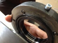
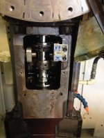
Fanuc Robodrill cartridge spindles are usually just swapped - not much online info about the bearings or innards available. So I've put together a few pics for the benefit of anyone wanting to take a peek. This spindle is from a 2005 D type with standard 10K spindle, newer ones are very similar unless near identical. I'll add more info as the repair progresses.

The spindle was getting noisy (particularly in the 3000RPM area) and had excessive vibration. The top end was out of balance: the flexi-coupling and drawbar actuator had 0.06mm TIR (0.5um allowed). I bought the machine in this condition so I have no idea why.

The top end bearing race has mangled the seating area as you can see from the pics. Runout was still excellent and the spindle felt smooth when rotated by hand but the noise was definitely not normal.

I apologize for the pic quality, these were for our reference only. The order shows the way the parts came off the spindle unit.

Pics: (invented names..)

1 Drawbar fixing system (2 M4 screws, large pin through)
2. Locking Rings
3. End plate
4. Bearing retainer with springs
5. Pressure plate

Regards,
Harri/Finland
 

Attachments

  • IMG_3422small.jpg
    IMG_3422small.jpg
    43.8 KB · Views: 3,496
  • IMG_3423small.jpg
    IMG_3423small.jpg
    58.1 KB · Views: 2,857
  • IMG_3424small.jpg
    IMG_3424small.jpg
    56.7 KB · Views: 2,507
  • IMG_3425small.jpg
    IMG_3425small.jpg
    59.8 KB · Views: 2,948
  • IMG_3426small.jpg
    IMG_3426small.jpg
    60.4 KB · Views: 2,159
More pics...

1. Lower end end cap (spindle gear has been removed previously, 8x M4x16)
2. End plate
3. end plate o-ring and blocked air purge inlet
4. NSK 7911C angular contact matched pair with spacer, showing alignment marks
5. bearing set orientation

IMG_3428small.jpgIMG_3429small.jpgIMG_3430small.jpgIMG_3431small.jpgIMG_3432small.jpg
 
Last edited:
and more..

1. spacer tubes
2. bearing spacers taken apart
3. bearing seat damage (top end), o-ring

IMG_3434small.jpgIMG_3433small.jpgIMG_3437small.jpg
 
Thanks for posting these. I'm always interested in seeing different spindle pictures (or machine pictures of stuff that you normally don't get to see).

Cheers,
Matt
 
The seat is an integral part of the cartridge. It probably needs re-coating and grinding but I'll know for sure when a bearing specialist has taken a look. I'll check fit and roundness, these should give some indication of the condition. The damaged top end has a somewhat unusual setup; one angular contact bearing (NSK 7008C) with light spring pre-load. I assume this is meant to keep runout to a minimum while sucking up thermal growth. Usually the top end has a deep groove bearing or an angular contact pair with some kind of pre-load.
 
Replacement is around 4400€ or 4700USD including the drawbar and spindle gear that engages with the toolchanger. These parts have been slightly modified on newer models and spare part spindles so that Fanuc can make you buy the extras ;)

Unfortunately the Spindle motor has a bearing failure too. Changing the bearings would be simple enough without the encoder, which makes the motor non-serviceable, according to Fanuc. The encoder appears to be pressed or shrink-fit directly onto the end...
IMG_3449small.jpg
 
Replacement is around 4400€ or 4700USD including the drawbar and spindle gear that engages with the toolchanger. These parts have been slightly modified on newer models and spare part spindles so that Fanuc can make you buy the extras ;)

You might want to check with Fanuc on a new spindle because as of December 2014 there is a new spindle and drawbar that can handle 1000psi coolant through. I can't say for sure on yours but the 24K RPM machine I bought in 2013 can be field retrofitted with the new parts despite the party line that they are not backwards compatible.
 
Thanks TKassoc, I might be a little late since a new spindle arrived yesterday.. But I'm still going to try to fix the old one.
 
An update - the why...

My bearing specialist visited and looked long and hard at the machine and the bits that came off it. This had bugged me too, no clear evidence of any crash, every screw in the mechanism was really tight, yet, massive runout on the coupling part.

Being a bearing specialst my friend came up with the most probable cause and we even found some evidence to back it up. Runout on the flexible coupling meant that something must have moved. Unless it was them Gremlins with little hammers, something else must have moved the middle section.

The coupling is of the disc type, with 3 screws up and 3 down. The disc had slipped very slightly, leaving the system misaligned and unbalanced. One of the screw threads even had a mark where the disc had hit it with considerable force. This was most likely caused by an abrupt spindle stop (crash, stuck toolchange etc.) The combined peak torque of the motor and inertia can do this - we calculated a rough estimate of 200Nm to make the coupling slip.

Anyway, the new motor is in and everything will be balanced tomorrow. The machine should be running again!
 
That suck you had to get a new motor per fanuc. I have seen that encoder arrangement in the past and it never stopped the local motor shop from rebuilding the motors. The encoders are pretty sensitive though and recommended to be replaced at the time of motor rebuild. Often this was skipped and all was fine.
Thanks for taking the time to share with us.
 
just trying to understand as I don't know much about a Robodrill is the spindle motor right on top of the spindle hooked together with a coupling disc no belt is that correct?
 
Yes it is direct drive. The motor and spindle are in line with each other in perfect alignment with a coupling between them. I would love to see a photo of the coupling if you have one.
 
That suck you had to get a new motor per fanuc. I have seen that encoder arrangement in the past and it never stopped the local motor shop from rebuilding the motors.

I've had a few Fanuc spindle motors with similar style encoders rebuilt by a local motor shop. Never had a problem with pulling off the encoder ring and pressing it back on. A drop of Locktite 290 was added post assembly to ensure it stayed in place.
 
Here are a couple of quick pictures.
IMG_3461 small.jpgIMG_3462small.jpg

The lower flange, upper flange and disc need 0.1mm of clearance. This forces the disc into a wave pattern and enables the necessary flex. Aligning the spindle unit and spindle motor (described in the manual):

-loosen motor s crews slightly
-loosen lower disc screws slightly
-run at 2000RPM until motor is correctly seated
-carefully tighten motor screws in cross pattern
-tighten disc srews
-check for runout with DTI
 
Yep, Mori gone, Robodrill in. We used to call the Mori Seiki a "Sorry Makey", no I'm not so sure anymore ;)


Back
Top