What's new
What's new

Rotary fixture to accommodate wide range of parts

GiroDyno

Cast Iron
Joined
Apr 19, 2021
Location
PNW
This idea was brought up in another thread but I think makes more sense to have its own discussion.

Here's some background on the current process:
These parts are cast iron rotors. They get turned in a few ops on VTLs, then front/back milling on a mag chuck in a VMC, and a perimeter engraving on one of those obnoxious pneumatic machines. In the VMC we load one part right side up and one upside down so every cycle get one finished part.
The front/back surfaces get grooves, the ID flange gets the lobed profile and we add slotted holes. There is no cutting of the OD.
Tolerance on the holes is -0/+.002" otherwise +/-.005". These parts need to be held very flat, the grooves make it very obvious (visually) if a part was milled at any sort of angle. I added a probe routing (thanks to some help from the other discussion!) to verify parts are loaded flat that runs on each part.
We have a range of ODs from 10.787 to 16.142" and thickness from .748 to 1.417".
They get a logo, part and batch number engraved on the perimeter that is maybe 3" long.
We machine specific parts #s in batches of 10-50, these are just based on customer orders so its more or less random how many/what parts are getting made. On an average day we probably switch between 5 different sizes and do 100 total parts.

Someone suggested skipping the mag chuck and loading parts into a rotary fixture and getting two complete parts every cycle. There are a couple other benefits like chip clearance and we could do the engraving so I'd really like to make this work.

I made a rough mock up to verify parts and tools would clear the machine, but now I'm stuck with how we actually would hold the parts. The face grooves go from the ID to OD, the range of diameters is large, and flatness is important.
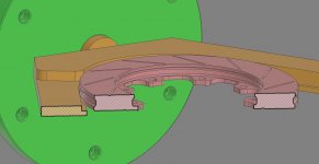
My first thought was to cut a wide V to constrain X/Y, a narrow lip for Z, and an opposing clamp to lock it all into place. However the lip must be very narrow to avoid the face grooves, and the max stroke for a clamp would be 5.5" so holding parts level seems tricky.
Then I thought about adding toggle/swing clamps to hold it down onto the lip, but because of the 4.5" span of contact along the edges these clamps would need to be adjustable which adds a setup complication...
Maybe we have a drop-in insert specific to a smaller specific range of sizes with its own clamps? Or...?
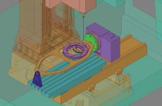
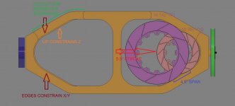
BASIC_LAYOUT.jpg
DETAIL_LAYOUT.jpg
SECTION_LAYOUT.jpg

I've been looking at this for a bit now and feel stuck, another set of eyes might be able to see an obvious solution. I'm hoping some creative people out these can help me figure this out!
 
Last edited:
I would skip doing 2 at a time and make a solid plate where you can put a part on one side and another underneath.
This would make your fixture shorter and a lot stronger, and then you could make different mounting attachments for each size that would bolt/dowel to your fixture plate.
 
I would skip doing 2 at a time and make a solid plate where you can put a part on one side and another underneath.
This would make your fixture shorter and a lot stronger, and then you could make different mounting attachments for each size that would bolt/dowel to your fixture plate.

At first glance that fixture looks flexible / flimsy to me. I'd be concerned about deflection.

Clamping to a plate or a rotary is pretty much what we do, without a rotary, but then we could do the engraving which I like. But I'm not sure if replacing a relatively simple offline process with a more complicated integrated setup is worth the effort.
We could put two mag chucks on a rotary and double-up our current process (4 parts), and do engraving but I could see an operator turning off the wrong magnet and parts falling off...

Or just do one rotor at a time (as pictured) and have a shorter fixture? Again not sure if there's a big enough advantage...

Consensus is the window frame might not be rigid. I can't imagine there is any significant amount of cutting pressure on these parts, holes are interpolated, the flange has a bit of radial load but that shouldn't cause it to potato chip... My gut says its mostly weight of the fixture/parts that would cause deflection. Even with a support on the end would that be an issue? 60lbs in parts and maybe 100lbs in the frame? I haven't designed a rotary fixture beyond a simple single sided trunnion/vise mount, so I'm not sure what is a "reasonable" weight limit.

I am totally willing to accept the setup as pictured might not be a viable process, but there are enough benefits that it feels like its worth investigating for a day or two.

Thanks for the input!
 
I think your diameter range is too big for one fixture. You need multiple fixtures to cover it. The design also looks way too flimsy. Needs to be much stiffer.

The rotors in a given size range have basically the same slots in them right? Group the rotors together based on sharing slot geometry and build a fixture for each group.

How many groups is that?
 
Before I'd invest too much time into it...try to machine a simple fixture and hold your parts in it. I'd be shocked if the parts held to your tolerances.

Flipping, deflection...trying to relocate fixture on setup to repeat. I'd have to prove to myself that it would work. I think you have one of those Because you can draw it, doesn't mean you can make it. Then comes the - what happens when operator screws it up... what's involved in repairing, redoing.

I could see the rotor moving in the fixture when flipping with light duty clamps. Might require higher clamping force to just hold the part under its own weight than is needed for actual cutting.
And good point about crashing/repairing. Its easy to get caught up thinking about all the ways to make something work, also need to imagine all the ways I could break it.

Maybe I'll work on a rotary mag table. Just need to figure out how to prevent the operator from turning off the wrong side...
 
I think you can do it, but not by pushing it into a V and the fixture will need to be much stiffer.

How much size difference for the ID of the rotors from biggest to smallest?

I believe the key to designing an effective fixture for this will be taking advantage of slot geometry (or where the slots aren't) and designing a simple mechanism that can center the rotor and pull it against a fixed surface.
 
There is a bit of an institutional problem here where nobody wants to reprogram anything that already exists and works. We are always struggling to keep up with orders, year after year we sell more so we have to make more, and are constantly adding new products to the line, so we don't really have the bandwidth to revisit existing programs once they are proven to work. Not to say things can't or don't change, it just takes a bit of arm twisting to get all the relevant parties onboard.

We design and make all our own parts, to our own specs, so we could standardize the slots to stay a set distance from the OD, we could also standardize the number of slots per size or overall. But nobody wants to do it, and nobody wants anybody else to do it either for fear of messing something up.

Rotors range from 10.787 to 16.142 OD, I just checked and we have 59 different ODs spanning that range. We also have thickness from .748 to 1.417.

When everybody says stiffer, what do you exactly mean?
Is the fixture not thick enough?
Is the rotary interface not sufficient?
The actual rotor clamping needs to be stronger?

Cast iron isn't all that tough, and enough material has been removed by this point there aren't any surprise hard spots or inclusions to worry about so cutting forces are low. The heaviest parts weigh <30lbs so with a support it doesn't seem like a lot of weight for the rotary to flip.
 
So I figured out who you work for and looked at all your products. Holy shit you guys get a lot of money for a few bucks of cast iron! $300 a rotor is insane!

How about you use a 3 jaw hydraulic lathe chuck or two with a body diameter small enough that your toolholder can reach past the body to mill the slots. For different sized rotors you just swap the chuck jaws. Depending on what kind of chuck you use this could be a few seconds to swap jaws.

You mount the chuck(s) in a steel plate with cutouts to reach through and mill the slots. Judging by the distance between slots in your pictures and your companies stance against drilling rotors this seems like it would be straightforward to implement.

I'm in the wrong business!
 
There is a bit of an institutional problem here where nobody wants to reprogram anything that already exists and works. We are always struggling to keep up with orders, year after year we sell more so we have to make more, and are constantly adding new products to the line, so we don't really have the bandwidth to revisit existing programs once they are proven to work. Not to say things can't or don't change, it just takes a bit of arm twisting to get all the relevant parties onboard.

We design and make all our own parts, to our own specs, so we could standardize the slots to stay a set distance from the OD, we could also standardize the number of slots per size or overall. But nobody wants to do it, and nobody wants anybody else to do it either for fear of messing something up.

Rotors range from 10.787 to 16.142 OD, I just checked and we have 59 different ODs spanning that range. We also have thickness from .748 to 1.417.

When everybody says stiffer, what do you exactly mean?
Is the fixture not thick enough?
Is the rotary interface not sufficient?
The actual rotor clamping needs to be stronger?

Cast iron isn't all that tough, and enough material has been removed by this point there aren't any surprise hard spots or inclusions to worry about so cutting forces are low. The heaviest parts weigh <30lbs so with a support it doesn't seem like a lot of weight for the rotary to flip.

To begin i don't like locating by od. here 1/2 mile a guys uses 3 jaw chuck which is correct method
otherwise dia. variation in od. dia. you loose your concentricity this guy does 125 pcs a day , a oriental guy in long beach using two old amura seiki drills 300 a day, I want it to get in that kind of work, but pay is real cheap, lot of work around here of that kind , most shop don't like cast iron stuff, they said ruin equipment , so the 100 pc lot is nothing to fear to this guys, they don't even check dia. of drill for tolerances they tell me is to get rid of gases when you brake.
buy yourself a used taiwanese mill a 3 jaw chuck for second op, like this guy do and home free.
 
The secret is to sell premium consumable products at a premium price to people with money to burn I guess!

You're suggesting using very small chucks with very long jaws correct?

If we were to reprogram parts from scratch to do both ops and add the engraving it would be easy to standardize our slot layout at the same time. Problem is I have to get buy in on this process before I can get the slots moved, but moving the slots would make this process easier to design, very much a chicken and egg situation.
They don't use small is like 12" or 15" manual scroll chucks and alum jaws no overhang, real simple stuff
is a easy work, just i hate to do it, warehouse are cheap they bring tons of those from overseas as blanks to customise i guess, old friend is in that kind of work and cast iron caliper.
 
Why try to make qty (1) universal "Does it all" fixture ?
Clearly some new parts will come into your shop, and then what ?

Your chances of setting the wrong part in the wrong section goes way up.
Also your fixture is going to look like swiss cheese.

I would come up with a inexpensive base plate to engage the rotary table (a sub plate)
Machine your rotary to have a central rabbet fit, and a diamond dowel for timing.

Example, a burnout of 1.25 thick M.S. plate, annealed, and Blanchard ground both sides
is not that expensive.
 
Why try to make qty (1) universal "Does it all" fixture ?
Clearly some new parts will come into your shop, and then what ?

I would come up with a inexpensive base plate to engage the rotary table (a sub plate)
Machine your rotary to have a central rabbet fit, and a diamond dowel for timing.

Example, a burnout of 1.25 thick M.S. plate, annealed, and Blanchard ground both sides
is not that expensive.

We are not a job shop. These machines are dedicated to this single product in its various flavors. All new part numbers will be just like the 300 other existing part numbers, except a few thou different here or there. This setup is for our bread and butter parts, if I can make 80% of our volume with 50% of the effort that's great.

Like you say something will come along that doesn't fit this setup, we have a cell for prototyping and "weird" parts because there are already are some that can't fit our universal fixturing.

As mentioned before a big plate is what we already have, a big plate on a rotary doesn't help enough to justify changing over from our current universal-but-boring mag chuck.
Or are you suggesting multiple fixtures to cover different sizes and a quick change system on the rotary? That's kind of what I was getting at with putting drop-in inserts in a more permeant mounted "frame"
 
The new parts will be just like the 300 other existing parts, except a few thou different here or there. This setup is for our bread and butter parts, 80/20 rule applies and if I can make that 80% of our volume take 50% of the time that's great.
Like you say something will come along that doesn't fit this setup, we have a cell for prototyping and "weird" parts because there are already are some that can't fit our universal fixturing.

As mentioned before a big plate is what we already have, a big plate on a rotary doesn't help enough to justify changing over from our current universal-but-boring mag chuck.

DO you really cast them here US, if so deserve lot of credit, its a super competitive market i live in a
city which is the capital of car wheel and rotor brake, several warehouses bringing from India, pakistan
maybe korea etc. of all places. huge market
 
DO you really cast them here US, if so deserve lot of credit, its a super competitive market i live in a
city which is the capital of car wheel and rotor brake, several warehouses bringing from India, pakistan
maybe korea etc. of all places. huge market

We've always been getting castings made in the US.
We have several custom castings that we are able to get 100s of different rotors out of. That's part of the problem with all our fixturing is everything is similar, but just different enough we can't have anything truly universal, but were pretty close. Two piece rotors add to complexity because there's no bell to help maintain rigidity and rotors like to warp, another reason they aren't finished on the VTLs.
If we only made a couple different parts it would be easy to buy a brake specific machine and crank them out, but because we have such a high mix wed spend more time setting up and tearing down than actually making anything. I see them for pennies on eBay and think about how to make it work constantly.
 
I think your proposal is too complicated and too slow

20x40 VMC should be able to hold 4 parts, 2 off every cycle. [edit] OK maybe not for 16 inch discs]
Seems pretty simple machining, so your toolchanger is probably not full for any good reason. Means a right angle head could do the engraving on the edge rather than spinning the whole thing. But still even 16 inch diameter, 4 hub centric fixtures and you could probably still fit 4 in the flat and 2 on edge a the end of the table, if you have a 40x20x20.

concentrically located fixtures with 3 point support with a clamp on each point. Discs set on 3 vertical pins, which should stay pretty clean if they never stick out from the edge of the disc, less time wasted blowing things off.

12 clamps to open for 4 parts, parts oriented A-B A-B left to right[for instance] 2 discs held vertically at the right end of the table by a previously machined bolt hole, defining the height for engraving. A simple clamp again can hold two discs at the right since the location of the text is non critical.

Process is:

Open door

Unclamp 2 vertical discs and slide off the pin, they are done, pivot right and set on cart

unclamp two B discs and slide onto vertical fixture

unclamp two A discs and set on B fixtures.

pivot left take two new unmachined discs off the other cart and set on A fixtures


clamp clamp clamp clamp clamp clamp clamp [two hands 14 total clamps]

I bet 30-45 seconds[okay they are heavy, maybe more] door to button time.

Fixture centers never move

The only dimensions that change are the vertical offset for disc thickness and the vertical offset for engraving, and perhaps the x offset for engraving.


Truthfully 10 parts on order for a stock part does not mean making 10 parts. It is usually cheaper to run them and hold them. Sure sometimes but if it is your product I think you will make more money by cutting lead time than saving shelf space.

Truthfully a lathe with live tooling would probably be the thing to do. Once it is on a machine let the machine to the work


Back
Top