Good Day
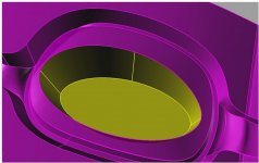
have a question for the veterans. How do you measure the geometry of a inclined slope geometry? Assume that the geometry is a oval cone to machine , and don't have a Probe ( Renishaw ,etc ) are there any tricks to see if the geometry is actually what it should be?
Tryed different aproches but it's not easy? Any idea?
Thank you kindly
Peter
Dexta