What's new
What's new

tailstock to rotary alignment issues.

MULTUSB200

Plastic
Joined
Feb 13, 2016
Hello friends.

Recently we've had a job running a very precise part that is approx. 12"x14"x5" cube with a few profile to datum callouts that require the fixture we work on to rotate around the 4th axis with less than 0.0004" of runout.
This means the fixture (aluminum) was milled flat and than rotated +90 - 90 and checked for parallelism with the machine's X axis.

Manipulating the tailstock proved tricky so a fixture was designed to hold the part on a fixture that mounts on the 4th axis, however when the fixture rotated +90 - 90 we saw the about 0.0004" runout aswell.

I am assuming the 4th axis is accurate and runs true (kitagawa mtx on brand new okuma mb machine)
I thought the problem could be the perpendicularity of the 4th to the table.

My question is - how common is it to put a grinding wheel in the BT tool spindle and grinding the face of the 4th perpendicular to the table and parallel to the YZ plane of the machine?
ever heard of anyone doing that?
 
Grinding the face of the platter when you've got all new shit?

What's next, facemilling the table "flat"?

If you cut the top flat, and at ±90° it is not straight in y, that means the axis of rotation is not aligned with X in the z-direction. <.0004" over 12" might be asking a little much. Could try shimming under the base of the rotary to improve alignment in XZ.

Or how about using multiple workoffsets for different features?

Or better fixture design. How is the end supported?
 
To echo what thesidetalker said above, if run an indicator across the face of the rotary, and you see that it is not parallel to y or z, trying to grind the face flat in yz would only make it worse when you index it around.

I don't understand what you mean by "manipulating the tailstock proved tricky"; are you using a tailstock?
 
@MultusB200 If you can make a video of where you are pulling these measurements from / how you are indicating that might be super helpful (more dynamic) and 'We" can see your set up.

Some rotary tables DO have a runout of the order of +/- 0.0002" or greater even. [It's not a lathe spindle.].

And there is the possibility of minor (angular wobble) in the bearing so that might have an effect depending on your fixture design and part length. [Shouldn't be a problem with a different approach to fixture design / part supported both ends/ tail stock or trunnion style support with separate bearing unit.].

I've seen set ups where the rotary table is used just as a driving mechanism via a coupling to a much more precise fixture with a separate bearing unit / fixture.

In situ grinding has its own problems … So I'm sure there are other ways to skin this cat before one would ever have to resort to that for your application (assuming I understand what you intend to grind in-situ.). Remember on a jig grinder your RPM is gonna waaaay higher than your MB spindle and the Rotary table moves really slowly (if I understand what surface you have in mind to "re-grind" (maybe) lol ).
 
The title says "tailstock to rotary", plus he mentioned adjusting the tailstock, so using my masterful powers of deductive reasoning---I think he's using one.

As to the answer in the title, the OP needs to determine what is out and where, then if it's within reason to correct it. Just going to town with a grinding wheel in a Toolholder would be getting ahead of himself. Determine error first, then determine course of action.

R
 
photos and further explanation

Ok thank you for your replies,
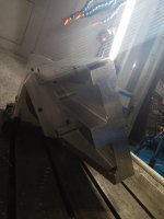
here is an attached image.
to make things clear - once we've failed to reach runout < 0.0004" with a tailstock we've abandoned the tailstock and made the fixture in the attached picture. it is mounted directly on the face of the rotary.
as I see it - once the runout in the +90 - 90 is EQUAL on both sides when running the indicator along the X axis - i.e the fixture runs out in the same direction (outwards as we move farther away from the rotary) this means the rotary is parallel to the Y axis of the machine.
however - because the fixture was milled flat in the XY plane and than rotated +-90 and showed runout I assume this has to do with the rotary to table perpendicularity.
I have to add that it is difficult to indicate the rotary because there are slots and a big bore on it's face and the indicator jumps on them making the reading not as reliable when searching for tenths.
I will have to attach a long parallel to the face of the plate to reliably measure this.

anyway, I figured once we're in the precision manufacturing business - what is more accurate than to grind the face of the rotary on the machine? assuming one has the right tools and knowledge?
of course for this type of adventure I would have first attached a dummy plate on the 4th and ground it off to eliminate the chance of harming a 30K$ piece of equipment.

IMG_20190411_075938.jpg
IMG_20190411_075931.jpg
 
Ok thank you for your replies,
here is an attached image.
to make things clear - once we've failed to reach runout < 0.0004" with a tailstock we've abandoned the tailstock and made the fixture in the attached picture. it is mounted directly on the face of the rotary.
as I see it - once the runout in the +90 - 90 is EQUAL on both sides when running the indicator along the X axis - i.e the fixture runs out in the same direction (outwards as we move farther away from the rotary) this means the rotary is parallel to the Y axis of the machine.
however - because the fixture was milled flat in the XY plane and than rotated +-90 and showed runout I assume this has to do with the rotary to table perpendicularity.
I have to add that it is difficult to indicate the rotary because there are slots and a big bore on it's face and the indicator jumps on them making the reading not as reliable when searching for tenths.
I will have to attach a long parallel to the face of the plate to reliably measure this.

anyway, I figured once we're in the precision manufacturing business - what is more accurate than to grind the face of the rotary on the machine? assuming one has the right tools and knowledge?
of course for this type of adventure I would have first attached a dummy plate on the 4th and ground it off to eliminate the chance of harming a 30K$ piece of equipment.

View attachment 254315
View attachment 254316
couldnt your .0004 problem be due to you machined it on the rotary?
maybe your table is off .0004 in that length of machining?

Just out of curiously how much does it move if you put pressure on the fixture?

what did you get for flatness on the rotary face going in the z direction(top to bottom) and the y direction (front to back)?

The other thing is that the weight of that 4th on one side of the table maybe adding to the issue. for example if your machine is not tight putting weight on one end will life up the other end slightl

that 4th axis seems to be well used, it doesnt look new at all,bearing preload could be bad in the 4th, or its not sitting flat and perpendicular due to table has a highspot or chips in there rotary bade.

what dia is that 4th?

I wouldnt use a tail stock, but would use a A-frame (more rigid) but still .0004 in not that much.
 
.0004? That is in the range of 1/8 turn on a leveling screw. Unless you have a foundation that weighs multiples of the machine you are going to be chasing this very often.

I'm with barbter, use separate fixture offsets.
 
after seeing what you have, I'd be pretty proud to say that my fixture is within .0004" at +/- 90. That is a lot closer than I would expect just looking at your setup.

Are you going to put a 14x12x5 block of aluminum on that thing? The added weight and it being off center is only gonna make it worse.

Another thought: I am not sure if I know how you are measuring the .0004" but some of that is likely backlash, since you are gonna have to go from 90 to -90, rather than 90 to 270. and with the weight off center, it would have a tendency to do that anyway.

It sounds like you'd have a much easier time running a job like that on a horizontal machining center. Much more reliable rotary for bigger stuff because you're not fighting gravity.
 
Ok thank you for your replies,
here is an attached image.
to make things clear - once we've failed to reach runout < 0.0004" with a tailstock we've abandoned the tailstock and made the fixture in the attached picture. it is mounted directly on the face of the rotary.

So I'm sort of defending my previous post here, but MAYBE you should start out with the correct information, as opposed to the wrong information. If you're not using a tailstock, you have a lot to contend with, the "gravity" of the situation is real. IMO you're getting pretty damn good results, for not having any support out there.

R


Back
Top