What's new
What's new

Tiny internal threading challenge I need a fresh idea

implmex

Diamond
Joined
Jun 23, 2002
Location
Vancouver BC Canada
Hi All:
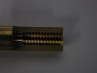
I've been handed a turning task that's giving me fits.

Internal 60 degree Vee thread 0.400" full threads long, 2 threads max lead out.
Pitch 0.03125"
Max diameter 0.146" +/- 0.001"
Root diameter 0.104" or 0.105" +/- 0.0003, 32 microinch or better
Pitch diameters 0.1235", 0.1245". 0.1256" and 0.1270" no tolerance specified.
Material 360 leaded brass. (Thank God for small mercies at least!)

Here's my problem:
When I run my threading bar (yeah it's TINY) the chips sometimes pack in between the bore and the side of the bar and scarf up the root diameter a bit, even though I've broken up the threading cycle into 6 separate cycles so I can fish out and blow out the chips frequently
So if I bore to 0.103", thread it, and then bore my finish diameter of 0.104" it doesn't clean up everywhere.
If I pre-bore to 0.100" I can't get a strong enough single pointing bar in to go 0.460" deep; there's just no space in there to accommodate the thread profile depth and the retract.

The thread crest is only 0.0024" wide at the root diameter...it's so damned delicate I can scarf it up just looking at it wrong or fishing out a chip too aggressively.

So I made up some custom taps to try that.

No joy on the taps, they scarf up the root even worse.
The problem is I have no room for clearance at the root of the biggest tap; it's currently a 0.001" radius which makes my root diameter of the tap 0.104" and it was the Devil's very own to get it that small.

Single pointing it and then chasing it with the taps makes no difference...I'll get a good one and then three crappy ones in a row.

So I'm looking for a fresh idea before I tell the customer I can't make his parts.

Someone send me a brilliant new strategy please!!

Cheers

Marcus
Implant Mechanix • Design & Innovation > HOME
Vancouver Wire EDM -- Wire EDM Machining
 
Why is the root diameter toleranced? It is non functional. It is clearance. It should be the pitch that is toleranced. What class do they call out on the dwg? I think that someone that designs stuff should be aware of its functionality.
 
Hey old chum,

If I were in your boots, I’d send the tooling out to have it ED Drilled and plumb it for through coolant. ( You didn’t specify that it has to be easy ) Following that, is threadmill it. Again, with through coolant to help with chip evac.
 
Hi littlerob1:
OOOHHH, those are cute!
They would almost do it too.
There are only two things wrong.
Not quite long enough (easy fix on the cylindrical grinder) and too big a flat in the root.

But the idea is Frickin' Brilliant!!!
I could get Alfred Lyon to maybe grind me up a custom single pointer.

So it's going to be 0.100" biggest diameter.
I need 0.021" per side for the thread depth.
I need 0.005" per side for clearance.
So the shank ends up 0.048" diameter and the tool is 0.460" long.

Will it survive???
That's the 6 million dollar question.

Thanks a million for the idea...threadmilling never even crossed my mind.

Cheers

Marcus
Implant Mechanix • Design & Innovation > HOME
Vancouver Wire EDM -- Wire EDM Machining
 
Hi revelstone:
As it turns out these are not threads, they're passages for some sort of mystery goo that no one will talk about because it's a secret.
So there's a core that goes into the part and apparently is pressed or shrunk or crimped in somehow.
The whole works needs to seal on those tiny 0.0024" wide flats but I don't know how well it needs to seal.

A failure is if the goo does not flow properly and the project is about finding a geometry that will make the goo do its thing and then figure out how to make a bazillion of them for pennies apiece.

So yeah; normally I'd agree with you, but sadly this is a special case.

Cheers

Marcus
Implant Mechanix • Design & Innovation > HOME
Vancouver Wire EDM -- Wire EDM Machining
 
Hi Zahnrad Kopf:
Yeah plumbing the cutter for coolant or HP air was a thought, but it's a LOOOONG way through a skinny shank and I' am already clenching my sphincter every time I push CYCLE START with that tiny scrawny little nail hanging out there a mile.
A thought I did have and broached with the customer is to try to buy heavy wall brass tubing like hole popping trodes and plumb the job instead of the tool.
I'd have to mount a rotary union on the spindle of the lathe and seal off the drawtube and the collet slots but it could work.
If it was just the thread I could pop it in the mill and do as littlerob has recommended, (easy to rig air through the part) but there are a bunch of other turned features and they all have to be concentric, so even if I do threadmill it it's going to have to be in the lathe.

On another note; why is it that people like you and I take on this weirdass shit??
Oh yeah...we are masochists who love pain...I think they call it a "challenge" in polite circles.

Again thanks for all the input everyone; I really appreciate it!

Cheers

Marcus
Implant Mechanix • Design & Innovation > HOME
Vancouver Wire EDM -- Wire EDM Machining
 
Hi Zahnrad Kopf:
Yeah plumbing the cutter for coolant or HP air was a thought, but it's a LOOOONG way through a skinny shank and I' am already clenching my sphincter every time I push CYCLE START with that tiny scrawny little nail hanging out there a mile.


Yes, but giving it a bore will actually make it stiffer, for the increase of surface area. Basic engineering.


A thought I did have and broached with the customer is to try to buy heavy wall brass tubing like hole popping trodes and plumb the job instead of the tool.
I'd have to mount a rotary union on the spindle of the lathe and seal off the drawtube and the collet slots but it could work.

Oof. That sounds a lot like work....


On another note; why is it that people like you and I take on this weirdass shit??
Oh yeah...we are masochists who love pain...I think they call it a "challenge" in polite circles.

I believe the word you are looking for is "hubris". Haha.

Make sure to post up how you accomplish it. :)

Be well.
 
I would check out the usual suspects; PH Horn, Micro 100, Vardex, Harvey, Emuge no idea if Mikron does Threadmills.

Good luck, R
 
Hi again guys:
Here's a picture of a reasonably good one.
This one only lost 0.0005" off the bore diameter right at the mouth of the bore.
Cycle time is about 10 minutes; much of that is for picking out the chips and blowing it out between threading cycles.
The 0.104" bore is 0.65" long and was single point bored too.
The blank diameter is 0.250"

Cheers

Marcus
www.implant-mechanix.com
www.vancouverwireedm.com
 

Attachments

  • dscn4698.jpg
    dscn4698.jpg
    97.3 KB · Views: 633
If you're going the custom tool route, how about using two tools. Let's say you're thread milling, the first tool has a truncated crest on it. Keeping your .100 OD on the tool, instead of .021 per side for the thread profile, you only need .011. This ups your shank from .048" to .068". Strength doubles and stiffness goes up by 2.8. You also may have room to do through coolant. The first tool is going to take out 3/4 of your material. You then finish up with a full profile tool.

You could do the same with a boring bar, but it's even better, because the full profile tool is going into a partially cut thread, you don't need to fully retract. Once you're at the bottom of the thread, just move a few thou in X and do a reverse threading cycle to get the tool out.

Last thought, could this be ram EDM'ed if the EDM had a way to synchronize C and Z axes? Basically rigid tapping with a ram EDM. EDIT: Looks like this does exist Don't Overlook EDM Tapping :


Modern Machine Shop
 
Hi revelstone:
As it turns out these are not threads, they're passages for some sort of mystery goo that no one will talk about because it's a secret.
So there's a core that goes into the part and apparently is pressed or shrunk or crimped in somehow.

The design is wrong, put the threads on the core and drill and ream the hole to fit. That has a much better chance of be able to be pennies a part.

CarlBoyd
 
A low effort way to experiment with coolant/air through the part would be to mount a milling coolant inducer toolholder in your spindle and hold the parts in there.

Do you have the means to program form following threading paths - to finish the thread in successive passes along the threadform with a smaller tool rather than a full profile one?
 
Hi again All:
You know, looking at the coarse pitch of the thread in the photo, I'm kinda wondering just how distorted it's going to be if I try to threadmill it.

Littlerob, you showed us a 6:32 threadmill from the Guhring catalog so obviously a usable thread can be made that way, but I wonder how much, if any form error it creates.
Have any of you guys ever sectioned a threadmilled 6:32 thread like this one and looked at it?

Regarding the idea of tapping it with progressively larger taps as you describe gregormarwick: it is a very good one and I used that strategy successfully on a part with a tiny double start Acme thread I showed on PM a couple of years ago.
The problem with this part however is that it's not a through hole, so the blind end becomes a problem especially since I have only two turns max for the lead-out so the taps would be equivalent to bottoming taps and I would have to blend that lead out without ever being able to see it without sectioning the part.
It's certainly do-able though.

Daniel G that's a great idea.
I like the notion of hogging out most of the meat with a stouter tool.
I encountered a problem trying to use a conventional threading toolpath with a full form single pointing tool; I couldn't keep the tip cutting when I got to the bottom of the thread because the engagement area was too big so the bar deflected.
So I broke the thread up into many small nibbles so no individual pass takes a full width or full depth bite; the tool is much pointier than the thread form it creates and there are a lot of passes to carve out the form without bending or breaking the bar
Your alternative would eliminate the need for many of those extra passes so I think it's a great idea.

CarlBoyd, the core has features on it too, so I sadly cannot do what you're suggesting.
The bulk of the channel has to go into the female part; it's a constraint of the design I don't get to tinker with.
I'm having enough trouble trying to convince the engineer responsible for the project to give me a few more thou on the root diameter so I can avoid the chip rubbing problem or just re-cut the bore to final size after the thread is cut.
Another couple of thou per side would turn the job from a hair tearer into a pretty straightforward project, but there just isn't room to give up very much and every thou has to be fought for because there are not many spare thousandths to go around.

Regarding sinker EDMing the thread, yes, Daniel G and metal, I did consider that as an option but there are a couple of obstacles there too.
The first is the concentricity of the other features relative to the thread; on the lathe I get it for free whereas on the sinker I have to work for it.
The second is the overburn and what it does to the thread crests...they're very narrow and easy to wipe out with just a tiny bit of secondary sparking from trapped cut debris and I'm not confident I could control it well enough to keep the crests pristine.
The last thing of course is the cost of burning the threads; I'd have to make trodes, set them up, change out and index finishing trodes and accept the relatively slow burn rate.

The hope is the customer is going to be able to take these off the screw machine at under a minute a part.
At this point we're still miles from there, but that's the stated goal.
Thankfully someone else will do that; I'm just helping to prove out the concept and determine what shape they're actually going to be.
But my machining solution does have to be scalable.
Cheers

Marcus
Implant Mechanix • Design & Innovation > HOME
Vancouver Wire EDM -- Wire EDM Machining
 
Regarding the idea of tapping it with progressively larger taps as you describe gregormarwick: it is a very good one and I used that strategy successfully on a part with a tiny double start Acme thread I showed on PM a couple of years ago.
The problem with this part however is that it's not a through hole, so the blind end becomes a problem especially since I have only two turns max for the lead-out so the taps would be equivalent to bottoming taps and I would have to blend that lead out without ever being able to see it without sectioning the part.
It's certainly do-able though.

Marcus, I didn't mean progressive taps, I meant to profile the threadform with a smaller tool. I'm not sure of the terminology to adequately describe what I mean though!

Others have called it rope threading on here in the past, but that is a different thing altogether and not the correct use of the term.

In my CAM I can draw a curve of the threadform and use a smaller tool, say a full radius grooving tool, to cut the thread by generating the surface of the threadform in successive synchronised passes, moving the start point for each pass. Sort of like a parallel milling toolpath with a ballnose endmill.

It takes a lot longer, obviously, but each pass creates a much, much smaller chip. It might be a solution to your chip fouling issue.
 
Yes, but giving it a bore will actually make it stiffer, for the increase of surface area. Basic engineering.

The central bore will increase stiffness per unit weight, but it won't increase total stiffness. Since the OD of the tool is fixed, the bore in the tool will reduce stiffness.
 
Marcus,

What's the wall thickness on the part when finished? How many parts?

How about grinding a fully heat-treated steel (or carbide) male part that has the correct shape/size/form, and roll swaging the brass down onto that "mandrel" and then unscrewing it?

... just trying to think of some other "outside the box" ideas. :crazy:


Back
Top