What's new
What's new

Turning, started to pull out tool holders?

Higgins909

Aluminum
Joined
Nov 19, 2018
Noticed that the back of the tool holders were almost flush with the chamfer of the tool slot. (3/4" bar? Slant style tool lock?) I have been trying to learn how to program this lathe and was trying to program a basic aluminum part I came up with. I didn't give it the max feeds and speeds either. (I did tell the 35 tool to cleanup at 700sfm .015X&Z though, only did that on the first attempt, didn't check toolholders)

I would have assumed I would break inserts before pulling the tool out? The machine had been sitting for maybe 3 months before I used it. I originally noticed it was the partoff and thought it was because it was only rated for some max DIA .800"~ and I used it to partoff a 1.5" part. The tool cleared it and my coworker was like what am I talking about when I told him the limit.

How did I start to pull the tool holders out? My coworker was a bit upset with me...

Thanks,
Higgins909
 
Do you have a smartphone? If so start taking pictures and posting them with your problems and questions so the group will have a better idea of what is actually happening.

If your turning up to a shoulder I'd leave less Z stock on the faces like the other guy suggested in your other thread posted a while back.

Did this place hire you to run a CNC lathe? What is the make, model and control of this machine?

Brent
 
Agree on taking a picture. I am confused at what you are trying to explain. Are you saying the tool holder itself came out of it's position in the turret?
 
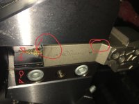
No, they didn't hire me to program anything. I've just been wanting to move up the ladder a bit and have been slow to do so. It's a Mitsubishi LT-350 with Navi and a M70 controller. It's got 4 manuals with typos and poor descriptions telling you to refer to this manual only to still not be told about the info I seek. Navi is a conversational programming language and it's looking to be quite horrible. So I started trying to learn Gcode. I think this is a picture I took before running the machine but I'm not sure. I was trying to find tool info as the angles of the tool holder were not programmed and are still not programmed... It looks like the left side of this tool, in this picture is already cocked outwards. (Looking at the top left) There were 2 other tools like this. They're fixed now but I wonder what happened to do it.

I've also included pictures of my part. Getting a bit off topic... With Navi I can't get it to face properly. The back end was bowed pretty bad from the part off being angled. Navi makes the rest of the part correctly though. I don't understand why it would only make the 1st step short. (DIA maybe .25 .75 1.25 1.45 each step is .25 and supposed to be 1" OAL) Right now I've given up on nave and have been trying to learn Gcode, so I can maybe understand Navi as it makes Gcode.

part front.jpg
part back.jpg
 

Attachments

  • part off.jpg
    part off.jpg
    89.6 KB · Views: 156
I thought it was the turn tool that fell out all I see is a pick of a cut-off tool and a part with a little chatter. As for the cut-off it looks like there isn't a lot of clearance between the holder and the insert. With that situation you have to get the speeds and feeds right to shoot the chips out of the cut also heavy flood coolant is recommended. The chip and galling issues are even worse if cutting a gummy aluminum like Chinese 6061. I always mount my cut-off on barrel turrets set the opposite rotations of yours on larger parts to shoot the chips up and out.
 
There should be a thin wedge that goes between the clamping block and the turret. I'm not seeing it, and the clamp looks like it's seated pretty deep. Make sure the wedge is there...

Also verify your shank size is correct for your turret. A metric shank in an inch turret or vise versa, the tool will not be on centerline.

Jancollc.
I thought the picture looked funny too. then if you zoom on it you can see the wedge on the left side(at least the step part)

the wedge or clamp could be in backwards ie taper on wrong side of clamp? that picture does look odd for some reason.
never seen a tool pull out, seen them cocked sideways but never pull out.

I was 1st thinking he was off center put the pic is deceiving. if he was way below center and clamp wasnt tight it might suck the tool into the part.
 
I found another picture and wrote on it a bit. (Work on Monday and wont see machine until then) The back side of the tool is pulling out and the front is flush. The wedge is 2 pieces? One has 2 screws and then a wedge with no screws goes on top (in this case) and then you put the tool in and start to tighten it. I have no idea how tight it needs to be or how tight it is now. When my coworker put it back together, he used a cheaterbar... None of them pulled out completely but they started to angle like in the picture. The gap at the back of the tool was somewhere of .050" and 0.100" while the front was still against the slot. I think the tool is .75" x.75" but I don't know for sure. The slot is 40mm tall x 20mm wide. I don't know of the dimensions of the wedges. I also don't know if it's making proper contact or if the wedge is screwed all the way in and not putting enough force to hold the tool. I will have to look Monday.

I told the machine to leave 0.1" so I could break it off. The machine wants to part off at 4000 rpm... (Still working on programming, slowly) I think it is just a groover but we use it to partoff too.

Theres a few problems i see here. I was thinking your tool pulled out. not cocked. Like vancbiker pointed out the tool is sticking out way to far.

alot of times you have to work with what you got. that groover blade will work

so heres your problems.
the tool should be set way back farther.
the guy who put the tool in the machine and the one who used a cheater bar to clamp it down should be kicked in the nuts.

take tool out clean the pocket and the wedge along with the clamp , put tool back in slide it back until you come close to the rad on the holder( otherwise you wont be flat) lock down the clamped screws. reset your tool both x and z

heres a pic to show you better. that gap is way way way too long. Again i had thought thats what you were saying pulled out.

The chatter is in the program the program, if the tool continues to move then you have programming issues or your tool isnt setting flat.
BTW the clamp should have a small air gap between the turret and the back of clamp. if it seats up against the back of turret slot its not tightening and your tool will move. make sure you have the wedge orientated correctly to the clamp. the angle side of the wedge goes on the angle side of the clamp. also make sure your clamp has the flat side up against the turret. with angled side on the wedge side.

Then when your all done kick the guy in the nuts again for being dumb.

part offa.jpg
 
And make sure the set screw in the center hole of the clamp is not poking out the backside and preventing the clamp from tightening up evenly. No way a cheater bar should be used- hand tight with an allen wrench is plenty.

I took it that the tool pulled out. It should be pushed in to that shoulder and re-tightened.
 
Sometimes tools have to be pulled out a bit because of clearance issues at center. I hope this isn't the case or this greenhorn is going to get a nasty surprise.

Brent
 
Something fundamental is wrong here. There is something that I cannot see going on. This is what I would do, if I were taking suggestions from an old Lathe hand. Based on the looks of that Holder, I would be doing a thorough inspection of it.

1. Take the Holder out, and put a Mic on the shank. (I suspect someone did some modifications/Machining to the thickness). If you find inconsistencies then you need to take some pictures, write down the dimensions, and re-post your findings. If not proceed to Step 2.
2. Take apart the clamp wedges and remove the Tool Block, clean and inspect for shittiness.
3. Stone all faces and mating surfaces for optimal Flatness.
4. Clean EVERYTHING
5. Put the wedge assembly back together, while it's benched.
6. Verify that your clamp wedge will actually close smaller than the Tool shank thickness that you now know from doing Step 1.
7. Re-Install Tool Block
8. Re-Install Tool Holder into the Tool Block, set back into the Block as far as you can.
10. Test the Tools ceterline in Manual mode, by chucking some stock and facing the stock with the Tool you just installed.

#101. Understand that when you are posting questions, using guessed names and incomplete descriptions, you are going to get shitty responses, because no one knows what you are trying to ascertain. Pictures, pictures, pictures. I realize you are new to this, so we are trying to help you.

Robert
 
Those double ended inserts usually have a max depth limit and with some of them things can go bad fairly quick if going much past it.
Though there's probably other funky stuff going on here.


Back
Top