What's new
What's new

Turret Indexing Problem

Triallyr

Aluminum
Joined
Jan 28, 2009
Location
Aurora, CO
I think I've read through all the threads concerning turret indexing but nothing helpful to my problem.

I have a CK1 lathe that indexes nicely going CCW but misses more often than not going CW (toys to clamp but is slightly off). If I manually rotate the turret (not calling a tool but just pushing the rotate button) it goes clockwise, so Im thinking something is worn or off on the CW rotation. I have adjusted the proximity sensors to no avail and the problem seems to come up more frequently as the machine warms up. Also, if I increase the hydraulic pressure to rotate the turret faster the problem gets much worse. Since it doesn't appear to be the proximity sensor (although I have a new one ordered just in case), could it be related to the hydraulic motor overrunning one direction or not clamping quick enough one direction because it has something worn from mostly going CW?

Thanks for your help,

Steven
 
I have no clue of the mechanics or electrics of your unit, but I have the same issue recently on my big lathe.

I'm kind'a wondering if it could be some lash on a worm screw?


--------------------

Think Snow Eh!
Ox
 
So I've been playing with the turret for a bit and it will clamp when I back off the hydraulic pressure and the turret rotates slowly. I'm starting to think the problem might be the slow down portion of the rotation. When the turret unclamps it rotates a faster speed and then, as it nears the called tool holder, it slows, making it easier to engage I think. There must be a way I can slow down the second part of the rotation while still keeping the fast initial rotation. Maybe a pressure switch or valve I can adjust?

Thx for any help
 
I'm going to guess that the hub of your turret isn't aligned properly.

Usually a ring of bolts pretty close to the center of the turret. (I
have not a clue as to what your machine is.).

Comes around one way and it locks in, come around the other way, and it
overshoots(or undershoots) and won't lock down, the curvic hits flat to flat
instead of taper to taper. Easy fix. Loosen some bolts and tighten some bolts
and you're done.

This can be aggravated (on a normal turret) by having all of your boring bar
holders on one side of the turret instead of spacing them out to even the
weight. Kind of like balancing a tire.

Did you happen to crash on a tool change right before this problem popped up?


Well... I actually thought it might be the curvic so I took the turret off, cleaned everything up and adjusted the curvic so it's dead nuts. It wasn't off by a lot (.001) but I got it down to .0002 and the problem remains unchanged. When I set the pressure low, the turret clamps fine both ways because it's rotating so slow but as I bring the pressure up to where it normally is, she almost always overshoots in the CW rotation. I guess it could still be the CW proximity sensor not picking up the next tooth quickly enough to stop the rotation but I'm not really sure how to test the sensor so its probably easier to just replace it when the new one arrives.
 
Testing a prox is simple.

All that I have seen have a light on it to show "high" signal.
Otherwise you could check the output wire for V.

Maybe you just need to adjust the prox closer?


----------------------

Think Snow Eh!
Ox
 
Testing a prox is simple.

All that I have seen have a light on it to show "high" signal.
Otherwise you could check the output wire for V.

Maybe you just need to adjust the prox closer?


----------------------

Think Snow Eh!
Ox

The light on the sensor goes red and then green just like the other sensor but no matter where its adjusted, it does not catch the turret at the right spot. Not really sure how the sensor actually stops the turret rotation. Does it just close a hydraulic valve or is there some type of brake involved? If just a valve, I guess the valve could be hanging up for a fraction of a second causing the turret to overstate...
 
I would have to guess some kind of by-pass valve, but I am not overly familiar with such item.


However - just b/c the OUTPUT on the prox is hig, does NOT mean that the PLC is seeing the signal.

At this point maybe you should try to flicker the prox and see if you can find any notice on the PLC?
If not - maybe try the one for the other direction and see if you can see that one?


---------------

Think Snow Eh!
Ox

When you say look for a notice on the PLC (I'm assuming this is the program logic controller?), what should I be looking for?
 
Typically a modern PLC unit will have indicator lights on the INPUT (or output) cards for each wire to indicate if it is on or not.
I don't know your machine, and .. well ... 1985 ... it may not have those?

Somehow you need to figger out if the control is seeing that prox input.

Maybe you can chase that wire down and see where it's hooked on the other end?
Test there.
Could simply be a break in the signal wire coming from the prox.


???


--------------------

Think Snow Eh!
Ox

The controller boards (main, servo, etc.) do have little green and red lights on them so I'll check that out with the turret rotating both directions to see if anything appears differently. Appreciate the suggestion, thx. Can a prox sensor go bad in that it starts to see a wider area as opposed to a very narrow band?
 
IDK about that or not really.

I think they either work or don't, but I guess anything is possible to some extent...

???


-------------------

Think Snow Eh!
Ox
 
What control do you have? If Fanuc of some kind, there will not be LEDs showing the state of inputs, they will be shown on a Diagnostic screen. The machine builder determines which addresses to use for which switch or sensor so you will need to refer to your schematic to see which address to look at.

There will probably be flow control valves under the solenoid valve that controls the high and low speed rotation. IIRC Yang included a hydraulic diagram in one of their manuals so it should be pretty easy to figure out how they are doing it and which valve is which.

Fanuc 3T. It does have a diagnostic button but I don't know much about working through it. I do have all the manuals and have been trying to work my way through the valve diagrams. Unfortunately, the diagrams don't label which valve is which but I located them on the machine based on the the indicator lights on the valves (Rexroth). I am also working through the schematics to see how the prox sensors and the valves work together. When the prox sensor goes green, does it just trigger the solenoid valve and that causes the hydraulic motor to stop instantly where it then clamps? Im starting to think it more likely that I have a dirty valve or it's hanging up causing a delay from the time it sees the signal if in fact the hydraulic motor is meant to stop instantly and go to clamp mode. Thx for your help
 
There is a programmable logic controller (PMC is Fanuc terminology) built into the control. The signal from the sensor(s) is an input into the PMC. The logic program in the PMC then will send an output signal to a relay that will control the solenoid valve when it determines that the turret is ready to be clamped.

How many sensors does your turret have. Often there will be at least 2. One for counting and location and another for clamp verification. Some builders use a pressure switch on the hydraulics though for clamping. Other machines will have a bit more sophisticated system and use 3 or more sensors and sometimes an encoder. It's been about 25 years since I last worked on a YAM and don't recall what system they used.

How all this works is determined by the machine builder since Fanuc has no idea what kind of lathe the control will be used on. For example a gang tool lathe or some swiss types don't have a turret.

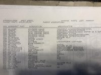
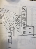
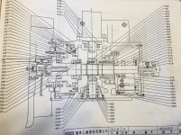
Post some pictures of your wiring diagram pages where it shows the turrets sensors. Also if there is a hydraulic diagram, post that pic too. That may give me something to work with to point you a bit more specifically at things to check.

If its any help our methods Slant 50 has a bunch for the turret. most of them are in the back of the turret assembly but 1-2 are in the front on the main shaft gears from the hydraulic motor that's in the back. you remove the cover and have access to them. we had the same problem. found the key way on the hydraulic motor was worn to crap enough to go the next tool and miss it.
got that fixed then it started doing the same thing after a few weeks. replaced the 8-10 sensors in the back of the turret assembly. ran great for a few weeks then started acting up again. problem was intermittent. so I assumed the wires were broke or loose. thats no easy task due to the way the wires the cable through the head and x axis. so mickey moused it running cables out the back of machine. Ran it for 2 months no issues. then started having problems again but rarely.
started looking again couldn't find anything wrong. looking at the electrical prints again they showed 2 more sensors but the weren't marked as for the turret they were marked as something else, but they were the same type of sensor. However we couldn't find those 2 sensors no matter how hard we looked. turret finally went down permanently.

started taking the tool turret assembly off the machine to try and figure out the problem, pulled all the covers off the turret assembly again , this time the one 1.5" x 6" cover on front side top way in the back and below 2 sets of gears I happened to notice 2 sensors barely sticking out pointing to each one of the gear dogs. replaced those it been working perfectly for 8-10 years. we had to take the X axis motor belt assembly and a shit ton of brackets and sheet metal to get to them put them in. you had to go through the sheet and they were covered up by the axis motor and belt assembly.
My turret dial had 1-12 even though it was a 10 station turret.

one other piece of info. the bar that holds all the sensors in the back is a thin alum bar that had a 90 degree bend on it. if its out of alignment with the dogs it will give you false readings and your turret will goto different positions from time to time.

I was told that alot of machines in this era had the same type of setup if they uses the mag sensors by a methods tech. he said they will have 1-2 in the front of the turret and the main ones on the back
 
There is a programmable logic controller (PMC is Fanuc terminology) built into the control. The signal from the sensor(s) is an input into the PMC. The logic program in the PMC then will send an output signal to a relay that will control the solenoid valve when it determines that the turret is ready to be clamped.

How many sensors does your turret have. Often there will be at least 2. One for counting and location and another for clamp verification. Some builders use a pressure switch on the hydraulics though for clamping. Other machines will have a bit more sophisticated system and use 3 or more sensors and sometimes an encoder. It's been about 25 years since I last worked on a YAM and don't recall what system they used.

How all this works is determined by the machine builder since Fanuc has no idea what kind of lathe the control will be used on. For example a gang tool lathe or some swiss types don't have a turret.

Post some pictures of your wiring diagram pages where it shows the turrets sensors. Also if there is a hydraulic diagram, post that pic too. That may give me something to work with to point you a bit more specifically at things to check.

4 sensors total. 2 sensors for clamp and unclamp position and 2 sensors for CW and CCW rotation working off of a 12 tooth dog gear. I have the ladder diagrams as well but don't really understand them enough to know if they're helpful. I'm going to take the turret's hydraulic valve apart today and make sure its clean. It has a speed control valve as part of it that seems to be related to the slowing down of the turret.

IMG_5061.jpgIMG_5062.jpgIMG_5063.jpgIMG_5064.jpg


Back
Top