I am machining plastic with a 10mm (0,39") ball nose endmill. I've used both morphed spiral passes and parallel passes to cut out a shape and I get varying heights on the top surface.
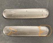
Where it says U the surface is higher, where it says N the surface is lower.
The upper part is made with spiral passes and the lower with parallel. The enlarged parts are of the spiral cut part.
The model for the CAM does not have these differences in height, and I can not see traces of this in the tool paths either. So I guess it is the machine. Any ideas what might be causing this?
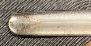