What's new
What's new

Yam / Yang CK1 Fanuc 3T No-Start - explain this circular ladder logic to me

Antarctica

Hot Rolled
Joined
Jan 16, 2007
Location
Annapolis, Maryland
Got an old Yam / Yang CK1 with a Fanuc 3T control. Machine has been down a while, but I've been working on getting it up and running again.

The machine will not power up enough to let the control turn on. I am 99% certain it is caused by Relay CR10 not being energized. I've swapped the relay, and done a lot of testing, but I'm confused by part of the ladder logic. Basically, the machine is stuck in emergency stop because CR10 won't close.

CR10 appears to be needed to power on the the main relay (CR1), but it also appears that the control needs to pull CR10's coil to ground to close it.

First Pic - CR10 being controlled by the control... The state of CR10 is also fed back into the control (I forgot to snap a pic of that but can). Also, why is there a big box drawn around CR10? I think its the only instance of a relay being treated like this in the whole ladder.

IMG_7720.jpg

Second Pic - CR10 needs to be closed on B02 and B14 for the machine to start up, so that the control can be powered up...

IMG_7722.jpg

Third Pic - The Emergency Stop ladder (the L19 LED is on)

IMG_7723.jpg

Any ideas?
 
For starters, the pictures you attached are of the electrical diagram (schematic) not the ladder. The ladder is a logic program that runs in the machine builder's section of the control (PMC). Do you have a hard copy of the ladder program? If so, you need to look at the logic that controls the output at Diagnostic 053 bit 0. That output needs to be on to actuate CR10.
 
For starters, the pictures you attached are of the electrical diagram (schematic) not the ladder. The ladder is a logic program that runs in the machine builder's section of the control (PMC). Do you have a hard copy of the ladder program? If so, you need to look at the logic that controls the output at Diagnostic 053 bit 0. That output needs to be on to actuate CR10.

Thanks for the response Vancbiker. Yes - schematics. I tend to refer to them incorrectly as ladders because their format is so much different than the schematics I work with on a regular basis (RF/microwave/digital).

I do believe I have a hard copy of the ladder program, but I don't think I need it yet.

I think I had my head around this wrong, expecting that what I posted was to allow the control to power up. But now I think those parts of the control don't matter until the control is up, and that's where its stuck. I need to go re-look at some things to understand more of what's (not) going on. Will post back results.

BTW, I did artificially make CR10 close, and the hydraulics and headstock lube came on, but the control still didn't.

Learning a lot about how these things were put together. Good education. Frustrating, but I'm enjoying it. Will enjoy it more if/when the display comes on!

Thanks again for your response.
 
Spent some time on this tonight. It's trying to come back to life....

If I depress and hold the NC power on button or depress it multiple times, the display tries to come up (It gets brighter/stronger the longer or the more times I depress it, so I presume that means the power supply/caps are coming up). I'm pretty sure the power on circuit isn't latching up, and I think its because the "PA-PB" relay on the control power supply isn't closing. According to page 195 of the 3T maintenance manual, that's caused by either the power voltages being incorrect t off the supply, or the control board getting some external error.

I set my multimeter to 'hold' while I depressed the button with it hooked to the +24 line on the control board and it measured 23.05, so at least that supply is good. I suppose I could do the same with the others...

I'm thinking of then pulling off the cables from the servos and spindle drive and powering it up to see if the error goes away and the control status powered up. Any issue with doing that? Good idea? Bad idea?

Other thoughts/suggestion?

I'll try to post a pic of the 'power on' circuit...
 
When you see the display start to turn on what is on it? See a position display of the axes? Having to power on multiple times or hold the power button to get the control on is often a sign that there are bad electrolytic capacitors in the power supply. It is prudent and inexpensive to change them all.

Removing the servo connectors and I/O connectors from the mainboard then trying to power up won’t cause any harm. You will get alarms and the machine will not power up fully, but you should get a position display and be able to switch to other screens if the control is good.
 
Thanks Vancbiker! Will try that tonight. That at least might prove out the power supply - or prove it bad. I might also move the display over to my other 3T machine to test it independently.

No noticeably bad (swelled, etc) caps but that doesn't mean they aren't. I don't try to hold the display up long enough to see what came up, but I think it was trying to display something. I recall planning to tune the vert/hor holds on this display prior to ignoring this machine, so its not easy to read. Nonetheless, the NC power supply is not staying up - probably the PA/PB latch thing. I don't really understand that circuit, but I haven't really studied it either.

Thank you for your help on this.
 
……No noticeably bad (swelled, etc) caps but that doesn't mean they aren't. I don't try to hold the display up long enough to see what came up, but I think it was trying to display something. I recall planning to tune the vert/hor holds on this display prior to ignoring this machine, so its not easy to read. Nonetheless, the NC power supply is not staying up - probably the PA/PB latch thing. I don't really understand that circuit, but I haven't really studied it either……

I’m going out of town for a couple days. I’ll look at the PA-PB contact circuit when I get back.

Old caps don’t have to look swelled or be leaking to be below their original rating and cause trouble. Noise from a power supply is also bad. Weak caps contribute to that.
 
From my read in the fanuc maintenance manual, it looks like the PA-PB relay is closed on the 3T power supply based on a logic level line change from the motherboard, based on the control getting an external alarm.
 
OK, a little more info, the plot thickens...

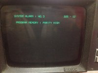
I took the display out and shoved it into one of my other machines to tune it a bit so it was readable. Then put it back in the Yang, and did the "Hold the power button" thing. It takes about 8-10 seconds for the display to come up, but when it does, I get a system alarm:

"System Alarm No. 3 D25-12

Program Memory: Parity High"

IMG_7738.jpg

According to the maintenance manual, one remedy for this is to boot while holding down the [delete] key which will wipe out the program memory. Tried that, but got the nearly same message, except it was "Parity Low". Powered it again without holding [delete] and it went to parity high again and back and forth, if the [delete] key is held.

As stated earlier, the power supply isn't staying on - its got to be 'held' on by depressing the control power button, so this thing isn't exactly in a normal state. Not sure how much faith I put in the above error at this point, but its something.

Also, I put the multi meter on 'hold' to measure various voltages while I held the power on button. All seemed to be fine, although the motherboard +15 was a little low (+14.66 I think I recall). I also looked at the +10 voltage reference on the power supply and it looked good, as did the +5 and +24 out. -15 on the hobo was also good.

Also, I unplugged the spindle control lines but nothing improved with the power supply staying up. I may try unplugging other lines tomorrow (servos, tool changer control lines, etc.).
 
Tonight I jumpered across the the PA-PB relay contacts and the control started right up (didn't even have to push the "Power ON" button. Same parity error.

The control power supply that the PA-PB relay resides on has an external alarm input that is supposed to activate the PA-PB relay. That alarm input is not connected to anything, so I think that means the power supply itself is setting the PA-PB relay (or the relay itself is not closing).

With the control parity error, it never sets the "Control Ready" relay CR10, so the E-stop circuit stays open. The next option on the control is to enable the parameter write and power it up again with the 'delete' key pressed, which will apparently blow its brains away, and I'll have to punch in the parameters I have written down - ...IF that step fixes the control, which at this point, I don't have much confidence in happening.

I have no idea why, but it looks like the motherboard may be sick. I pulled several of the interface cables off of it and keep getting the same error.

Doesn't look good, but I've narrowed down a lot...
 
A parity error is a memory error. Words in memory have one bit that says whether the number of bits that are data are on is an even or odd number. If a bit is bad, say a bit that should be on is off then the parity bit won’t match and the processor knows there is bad memory. Typically this is only checked on power up not all the time.
 
Thanks - I think I'm coming to the same conclusion. Reading through manuals and the web, I'm wondering if one of the EPROMS has taken a dump. Maybe I just need to pull the eproms from the other machine and burn a new set?
 
It’s not likely that it is a problem with an eprom.

Since you tried the memory clear without success, next step is to initialize all the memory. This will clear all your parameters, both CNC and Diagnostic. Be sure to have all these recorded/ backed up if possible.

If you do not have a good backup then the following would be worth trying.

There is a small chance that the parity alarm is being caused by electrical noise from the CNC power supply. <50mV is desirable. Often changing all the electrolytic capacitors in a power supply will clean it up.

If you do not have a good parameter backup and have to initialize the memory, it will be difficult to recover the machine unless you have access to data from a nearly identical machine.
 
The next option on the control is to enable the parameter write and power it up again with the 'delete' key pressed, which will apparently blow its brains away, and I'll have to punch in the parameters I have written down

Hello Antarctica,
If you end up initialize all the memory, you get a one shot chance of downloading the parameters to the control via an RS232 connection. The comms protocol are set at the control to Fanuc defaults of:

Data Bits = 7
Stop Bits = 2
Parity = Even
Baud Rate = 4800

Accordingly, if you get to the point where the control is on, it would be worth the effort of typing the parameters into a text file in the format required and then upload them to the control. If you dump the parameters from your other machine it will have the correct format and you will only have to change some parameters, rather than type in the whole catastrophe. In any event, typing the parameters into a file at a PC is a whole lot easier than putting them in by hand at the control.

If you have a copy of the Option Parameters, they can also be included in the upload to the control by pressing the EOB button when starting the upload.

Regards,

Bill
 
Power supplies are infamous for failing after a couple of decades, and can cause all kinds of headaches.

I would start with replacing your NC power supply, or rebuild it. (All new capacitors, possibly some transistors, diodes, etc.)

It sounds like the "start circuit" in your power supply could be bad, since it won't latch on, yet by holding the power-on button in, you get the needed 24 volts DC (close enough anyway).

There is a YouTube video by "Mr. Carlson's Lab" where he rebuilds a power supply for a Mitsubishi FR-SF spindle drive (used on older Mazaks). He discusses at length how the start circuit works for a power supply.

ON EDIT: Btw, Mr. Carlson on YT is one sharp dude when it comes to electronics diagnosis and repair, worth a watch if you're interested in those things...

ToolCat Greg
 
It’s not likely that it is a problem with an eprom.

Since you tried the memory clear without success, next step is to initialize all the memory. This will clear all your parameters, both CNC and Diagnostic. Be sure to have all these recorded/ backed up if possible.

If you do not have a good backup then the following would be worth trying.

There is a small chance that the parity alarm is being caused by electrical noise from the CNC power supply. <50mV is desirable. Often changing all the electrolytic capacitors in a power supply will clean it up.

If you do not have a good parameter backup and have to initialize the memory, it will be difficult to recover the machine unless you have access to data from a nearly identical machine.

Thanks Vancbiker. I'll put a scope on the power supply tonight to see what it looks like. I'd like to solve the power supply issue before I wipe this thing out. I also ordered two used supplies to look at, and possibly make 1 out of the three, if I can find the problem. I need to solve that issue one way or the other, and I'd rather not wipe the machine if resolving the power supply issue somehow fixes the system parity error fault.

I have a hand written copy of the parameters, but I not the diagnostics pages. I thought the diagnostics were more or less outputs? Here are the parameters I wrote down (with my takisawa parameters also)

View attachment Yang_Taki Parameter Comparison 12_07_06.xlsx.zip

Did I not write enough down? There is another used on the forum that has a nearly identical machine. I might be able to get params from him.
 
Hello Antarctica,
If you end up initialize all the memory, you get a one shot chance of downloading the parameters to the control via an RS232 connection. The comms protocol are set at the control to Fanuc defaults of:

Data Bits = 7
Stop Bits = 2
Parity = Even
Baud Rate = 4800

Accordingly, if you get to the point where the control is on, it would be worth the effort of typing the parameters into a text file in the format required and then upload them to the control. If you dump the parameters from your other machine it will have the correct format and you will only have to change some parameters, rather than type in the whole catastrophe. In any event, typing the parameters into a file at a PC is a whole lot easier than putting them in by hand at the control.

If you have a copy of the Option Parameters, they can also be included in the upload to the control by pressing the EOB button when starting the upload.

Regards,

Bill

Thanks Bill -

I'm not sure I understand. The control won't come up (stuck on the page with the parity error), so I don't know how I'd be able to get a 232 dump of the parameters out of the machine. Am I missing something?

If there's some trick to do that, it'd be great!
 
Power supplies are infamous for failing after a couple of decades, and can cause all kinds of headaches.

I would start with replacing your NC power supply, or rebuild it. (All new capacitors, possibly some transistors, diodes, etc.)

It sounds like the "start circuit" in your power supply could be bad, since it won't latch on, yet by holding the power-on button in, you get the needed 24 volts DC (close enough anyway).

There is a YouTube video by "Mr. Carlson's Lab" where he rebuilds a power supply for a Mitsubishi FR-SF spindle drive (used on older Mazaks). He discusses at length how the start circuit works for a power supply.

ON EDIT: Btw, Mr. Carlson on YT is one sharp dude when it comes to electronics diagnosis and repair, worth a watch if you're interested in those things...

ToolCat Greg


Thanks toolcat - I'll take a look at the Carlson video on the start circuit. The power supply has to think something is wrong if it won't stay up (or the onboard relay is stuck).
 
………I have a hand written copy of the parameters, but I not the diagnostics pages. I thought the diagnostics were more or less outputs?…….

On the 3 series controls the PMC parameters are displayed and entered in the Diagnostic display. The range from 128 to 699 are able to be used by the machine builder for timers, counters, data, and keeprelays. You need to have those from an identical machine as their purpose and values are determined by the machine builder. These are often documented in the hardcopy of the ladder program.

CNC parameters from a similar machine from a different builder can be a good starting point. It still is a lot of work to verify and correct things like hardware configuration, spindle encoder resolution and ratio, servo encoder resolution, screw pitch, and if gear or belt drive between servos and screws that the ratios are the same.

Even if you do find your power supply is the root cause of the trouble and fix it, it is certain that you will need to clear the program memory and almost certain that you will need to initialize the control.


Back
Top