What's new
What's new

Abene VHF3 1964 spindle

jcge

Plastic
Joined
Sep 30, 2021
I have an Abene VHF3 circa 1964 with leaking spindle oil seal

A few years ago, when I acquired the machine, I contacted Fredrik Yman at Abene AB and he forwarded me a parts list/drawing set for my machine. Abene are now out of business (bankrupt in 2020) and the new owner (Vemu AB)have been unresponsive to my enquiries. There's very little info available on these machines...

2021-10-03_11h06_28.jpg
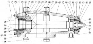
302.1xx spindle (believed to be my 1964 year model)

According to that documentation, it is equipped with spindle assembly with part number series 302.1xx and a bearing arrangement consisting of double row cylindrical roller bearing (I believe with tapered bore similar to SKF NN3010K) at the business end, and a single row angular contact ball bearing and thrust ball bearing at rear end (seems redundant....more to follow)

I'm currently trying to disassemble the spindle to fix the leaking oil seal and I'm looking for some enlightenment !!

Firstly, the rear bearings are actually SKF 6207 (a regular deep groove ball bearing, not an angular contact bearing as the drawing above suggests), and a SKF 51110 thrust ball bearing. A slightly later spindle model 302.2xx shows the bearing as a regular deep groove ball bearing, consistent with that which I have found. It's drawing section is shown below (and is much clearer in its detail to the original 302.1xx drawing above. (note there's a slightly different numbering of the components).
2021-10-03_11h29_50.jpg
302.2xx spindle (later year model)

With respect to disassembly, (and I've seen cwilcox's thread previously) I'm very nervous..
Abene Spindle Disassembly - Experience Requested

Referring to the drawing 302.2xx, I've removed all of the tail end components (18-29) except the deep groove ball bearing (17), and moved the circlip(12) which retains the bevel gear(10) toward the rear end of the spindle. It would now seem a simple matter of sliding the bevel gear along the spindle to allow the spindle to be pressed out trough its housing, the front roller bearing(4) being of separable design, and its outer race large enough to accommodate the bearing retaining nut(8).

More to follow....
 
Last edited:
Questions....

I have a some concerns regarding pressing the spindle from the housing.

1) So far, I've been unable to slide the bevel gear along the spindle (I've removed the circlip from its groove), and I'm concerned that upon reassembly, I wont be able to return the gear to its position, given what seems to be a solid press fit betweeen it and the spindle. How is this achieved upon reassembly ?

2) Can anyone confirm that the front spindle bearing is in fact a separable double row cylindrical roller bearing (with tapered bore) similar to SKF NN3010K ? The arrangement of this machine (circa 1964) is definitely not that of 302.4xx which features back to back taper roller bearings.

3) Assuming that question 2 above is confirmed as a separable double row cylindrical roller bearing....does the spindle simply press out of the housing through the roller bearing outer race (subject to the press fits of the bevel gear and rear deep groove ball bearing)? The OD of the bearing nut SKF KMFE10 should clear the ID of the bearing outer race

4) All of this has implications for the setting of gear mesh and clearance - the subject of a future post in this thread.
 
Spindle bevel gear mesh and clearance

Here's my take on the bearing arrangement and its implications for bevel gear mesh and clearance...(please do critique this)

2021-10-03_13h55_31.jpg

The front bearing, being a double row cylindrical roller bearing, cannot support any thrust load. It can only support radial load. The bearings radial internal clearance is set by tightening the lock nut(8) which drives it up the matching 1:12 taper on the spindle journal until it abuts the precision thickness washer(38) at the rear of the spindle head. The thickness of this washer thereby determines the internal bearing clearance. The thickness of the washer is determined prior to assembly at the factory, using external gauging to establish optimum radial clearance (or preload). This is consistent with how SKF recommends this type of bearing is mounted.

SKF

There are grub screws(37) in the spindle head behind the washer that facilitate removal of the bearing from its taper on the spindle. I don't think they play any part in the setting of gear mesh or clearance.

2021-10-03_13h56_57.jpg

At the other end of the assembly, the deep groove ball bearing(17) provides for radial location of the spindle. It's a press fit on the spindle, but floating in the housing. Its also the only element capable of absorbing the bevel gear thrust in the free running condition.

The thrust bearing assembly is the only bearing element capable of resisting the primary milling thrust load directed into the spindle. However, it cannot resist the thrust load generated by the bevel gear set in the opposing direction (see above). It's captured in position between and inner (18) and outer(23) adjusting collars. The collars being adjusted to deliver a slight preload, thereby eliminating spindle end float. The position of the rear most washer of the thrust bearing(19) is determined by the thickness of the adjusting washer(22). This is locked in place by the outer adjusting collar(23), secured in turn to the spindle housing by the rear ring(21). The inner adjusting collar(18) is threaded onto the spindle shaft and locked in position by the external nut(26) and its tabbed locking washer(25).

The bevel gear(10) is simply located on the spindle between a shoulder and circlip(12) and driven by a simple key(11).

So I've come to the conclusion that the bevel gear mesh and clearance is ultimately determined by the thickness of the adjusting washer(22) at the rear of the spindle (and corresponding shimming of its mating 23T gear on the head stock gearbox) but only once the internal axial clearances of the thrust washer AND deep groove ball bearing have been taken up by the inner and outer adjusting collars, whereby the bevel gear thrust is absorbed by axially loading the deep groove ball bearing.

For reference, the bevel gear on the headstock gearbox bears the markings SKF 1352874 and jp0.13 which I'm assuming is the clearance setting in mm. On the rear of one of the teeth, it is marked "64" which I assume is its mounting dimension in mm (relative to the axis of its mating gear).
 
hard to give an educated opinion. Pictures are way too small to see any details.
I am sure you have it figured out, this spindle would be a first in my experience.
Have never seen a milling spindle that had actual seals ...Almost always they use slingers and labyrinth type sealing, close fitting, but no contact....
Would love to see a larger version of the assembly drawings, or the actual parts when you get it apart....

Cheers Ross
 
Thanks for replying Ross - the images were highly detailed but are appearing as tiny jpg's.....I'm trying to work out how to get them to display properly.

Edit...detailed images now expand
 
Looked at the drawings...If they represent what you have then i believe you are correct in how this comes apart.
You need to remove the rear retaining nut (#26) along with the bevel gear retaining clip at the front (# 12). and retaining ring (front #3)

Then support the front of the housing and press on the rear end of the spindle.....
You will have to overcome the fit on the rear bearing (#17), spacer (#18) the bevel gear (#10) and the fit between the roller bearing outer race ( #4) and the bearing carrier (#5).

Looks likely that the inner and outer races of the roller bearing (#4) will just slide apart leaving the outer race behind in the carrier....
I would apply rotary motion to the spindle in steps if possible when you press it apart...(release the press tension rotate the spindle some then apply more pressure...rinse and repeat)
This will help the rollers slide out of the outer race.....

Looks like shim (#38) sets the axial position of the roller bearing being held in position by lock nut (#8) and spacer (# 7) and therefore the running clearance of that bearing.

Reassembly will be bit more difficult. I would remove the rear bearing (#17), the thrust bearing (#19) and the Sleeve (#23) to allow using a tube over the spindle inserted through the rear to press on the bevel gear once the spindle front bearing is seated.

Cheers Ross
 
Abene did use SKF NN series bearings in at least some of their spindles - there are photographs in the SKF book 'Bearings in Machine Tools'. The taper that the bearing is assembled to allows extremely precise control of run-out when the bearings are first fitted. This is described in great detail in the SKF book - it is not just a matter of tightening up a nut to a stop. If you really do have this type of bearing, I strongly suggest you get hold of the book and study it closely before you start on the spindle.

I have these bearings in both axes of my Thiel mill and I have to admit that I find the complexity of replacing them correctly intimidating to say the least.
 
Hi Ross - thanks for your review. Appreciate you taking the time to walk through it

The spacer (18) is threaded to the spindle and is easily removed, leaving just the press fits of the rear bearing(17) and bevel gear(10) to overcome..

I would apply rotary motion to the spindle in steps if possible when you press it apart...(release the press tension rotate the spindle some then apply more pressure...rinse and repeat)
This will help the rollers slide out of the outer race.....

Reassembly will be bit more difficult. I would remove the rear bearing (#17), the thrust bearing (#19) and the Sleeve (#23) to allow using a tube over the spindle inserted through the rear to press on the bevel gear once the spindle front bearing is seated."Cheers Ross


These two bits are GOLD - thank you. I had not considered using a tube to seat the bevel gear on reassembly.


Thank you.
John
 
Abene did use SKF NN series bearings in at least some of their spindles - there are photographs in the SKF book 'Bearings in Machine Tools'.
........
........the complexity of replacing them correctly intimidating to say the least.

Thank you for the reference - I'll try and track that SKF book down.

My objective here is to replace the leaking oil seal and grease the bearings.....replacement of that front taper bore bearing is not part of my plan for the very reasons you outline !! I have no reason to believe it requires replacement (yet...)

John
 
I have an Abene VHF3 circa 1964 with leaking spindle oil seal

Abene are now out of business (bankrupt in 2020) and the new owner (Vemu AB)have been unresponsive to my enquiries. There's very little info available on these machines...
Well that explains why I could never get an email response from them also.


Back
Top