What's new
What's new

Aciera F5 Overarm Support Bearing Fabrication

rklopp

Diamond
Joined
Feb 27, 2001
Location
Redwood City, CA USA
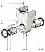
My Aciera F5 came with an overarm support from another machine. The bearing bore did not line up with the horizontal spindle axis. Rather than spend a whole ton of time scraping the interface between the overarm support and the overarm, I decided to accommodate the 0.015" offset by making a new bushing and boring it in situ. Scraping the interface would have involved trying to get at least four, and preferably five, angled surfaces to hit at once while getting the bore lined up correctly. The bottom of the overarm is shaped a lot like a Schaublin or old-style Hardinge lathe bed, so there are two angled surfaces plus a flat. The overarm bearing support has five seating surfaces, because there are big hollows between the each pair of angled flats on the side, as can be seen in the diagram.
Overarm Support.jpg
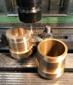
I got a piece of 3" cored SAE 660 bearing bronze off eBay and went at it. I got the taper fit by bluing to good contact with the tapered seat in the overarm support. The seat is a light press fit in the overarm support casting, so it was easiest to press is out to use it as a gauge. I cut the M58 x 1.25 threads using a single-profile thread mill in the FP2NC. I got lucky, because the two Aciera nuts had slightly different pitch diameter. I cut the thread oversize, and found one of the nuts already fit the oversize male thread, while the other would not.
Reassembled 5.jpg
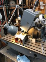
Then, I bored the bushing by butting the overarm support against an angle plate clamped to the mill's table and feeding the Y axis with a boring head in the spindle. This slide the overarm dovetail in its mounting, effectively pushing the overarm support and bushing toward the spindle. I kept the overarm support locks lightly snug to act as gibs.
Reassembled 4.jpgReassembled.jpg
 
After getting the bore right, I took the support off and cut two oil grooves on either side of the bushing by tipping the Aciera F4 head 25 degrees to either side and reaching in with a long 5/16" end mill. I attached from both side and met at the oil hole in the middle. This did not need to be precision work.
Reassembled 3.jpgReassembled 2.jpg

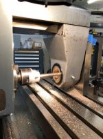
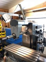
Here is the final product with a long antique 1" Brown & Sharpe arbor installed.
Reassembled 1.jpg
 
Nice work Rich.
Boring in place is the go to method for finishing plain overarm bushings.
Nice trick to use an angle plate to the cross slide....Did you clamp the plate rigid to the overarm or leave it have some compliance so as not to influence the true position?

Easier task on a Deckel having the horizontal quill. :)
Did you gauge or test indicate the finished bore relative to the spindle? At different extensions of the overarm?

Is the bushing split and drawn in on the taper to adjust the running clearance using the nuts like a collet? (Cinci horizontals do it this way)
Cheers Ross
 
Did you clamp the plate rigid to the overarm or leave it have some compliance so as not to influence the true position?
I did not clamp it, but just butted it against some rubber blocks placed between the overarm support and angle plate.

Did you gauge or test indicate the finished bore relative to the spindle? At different extensions of the overarm?
I did not do that. Probably should.

Is the bushing split and drawn in on the taper to adjust the running clearance using the nuts like a collet? (Cinci horizontals do it this way)
Cheers Ross

It is split and tapered, but there is also a fixed shim, part 15 in the diagram, which limits closure. I am not sure whether it is supposed to be clamped by the closed split, and thinned to do the adjustment, or whether the shim is supposed to remain loose and simply limits excessive collapse. I had a separate post about this. The shim is missing on my F4's overarm support*, and it works fine without it. Any thoughts?

By the way, because the bushing bore is offset with respect the OD, I added a pin to the support that engages a slot on the bushing to prevent the bushing from rotating while it is adjusted.

*The F4's overarm and bearing support are an integral casting. It is a beast to install, because first the vertical head has to come off the machine, and it is very heavy. On the F5, the vertical head is on a swing arm, so it just moves off to the side with no lifting needed. In addition, the F5 overarm is always present, and just needs to be slid forward and the overarm bearing support bolted to the outer end.
 
My feeling is that the shim would be there as a positive limit to the adjustment for clearance....
Just because the Swiss would want to set the clearance at the factory (new parts) and deliver it ready to go...with the ability in the future to grind/change
the shim thickness to compensate for wear ...would also calibrate the amount of diameter change...if the bushing was running at say.0035" clearance and the adjustment was tight up on the shim
at that clearance..and knowing the taper rate , then removal of a given thickness would result in reducing the clearance by a specific amount.....

Also can't tell from the drawing exactly...but think you would want the bushing to be secured, tight and that i think means using the shim to tighten against....

Cheers Ross
 
Also can't tell from the drawing exactly...but think you would want the bushing to be secured, tight and that i think means using the shim to tighten against....

Cheers Ross
The bushing is secured tight even without the shim, because there are nuts on each end that can pull against each other. When adjusting, you use one nut to pull the bushing into the taper and the other to pull it out. When you like the setting, you snug both nuts so they oppose each other. In my case, the added anti-rotation pin adds additional security.


Back
Top