What's new
What's new

Alexander deckel FP1 clone

bob531

Aluminum
Joined
May 9, 2015
Location
U.K Cumbria
Hi , Im new here, im in the north of England and the new owner of an Alexander master toolmaker.
Im busy removing parts to reduce the weight for to move it into my workshop.
Does anyone know how to remove the horizontal spindle housing from the top of the column?
Ive been following the Deckel instructions ,ive removed everything i can see which is in the way and have got to the part where it says tilt it to the right to clear the gear underneath and lift off (or is it slide it off ?). It just wont move !
Any help would be great!
Thanks Bob
 
Bob, did the headstock move OK in the Y direction before you started to disassemble? I assume yes. Have you removed the gib? If so, the headstock should have plenty of "wiggle". Is that the case? Cheers, Bruce
 
Hi :-)

You should disengage the leadscrew for y axis, in rear end. Then pull the (is it called gip?) Out, then the housing should be able to push sideways. And also forward. :-)

Hope it make sense. Else I can take some pics of mine


Maybe you can see something from my timelapse, of the rescent disassembly of my prvomajaska alg 100. Im also total newbee on this mill. But its a well build machine, and mostly easy to take apart :-)
ALG 1 tilspaending/power feed - YouTube
 
P1290015.jpgThanks for the replies, i followed the instructions in the 58 page Deckel manual as the Alexander manual doesnt go in to any real detail. Yes the Y feed was working fine before starting.
Yes i removed the y feed screw hanger at the back , also the feed screw and the gib strip.It lifted up on the left side around 2-3 mm but would not slide off towards the back . I could feel it still hitting the gear (or something).
On the suggestion of someone else i removed the horizontal spindle(which appears in very good condition) which took a few minutes and the horizontal headstock slid off no problem.
I don`t know if there is any slight difference between the Alexander and Deckel but it just would not slide off using the Deckel method.
If its of interest to anyone this Alexander serial number 1220 ,has a build date of 7th Feb 1956 and was supplied to the Louis Newmark watch & aircraft instrumentation company in Croydon .UK.


P1290002.jpgP1290004.jpgP1290005.jpg
 
Rasmush, great video! Did this take place over several days? If so, the next time you make a time lapse like this, you need to hang a calendar on the wall with one day per page, which is visible in a corner of movie.

Bob, glad you got it off! The spindle looks really clean, that's a good sign. Is the machine stored in a shed? Given that the UK climate is not exactly Arizona, do you need to worry about corrosion?

Cheers,
Bruce
 
Hi , Im new here, im in the north of England and the new owner of an Alexander master toolmaker.
Im busy removing parts to reduce the weight for to move it into my workshop.
Does anyone know how to remove the horizontal spindle housing from the top of the column?
Ive been following the Deckel instructions ,ive removed everything i can see which is in the way and have got to the part where it says tilt it to the right to clear the gear underneath and lift off (or is it slide it off ?). It just wont move !
Any help would be great!
Thanks Bob
Some of those copies might come out the front better than the rear. Calling another machine a clone gets kind of iffy as a different manufacturer can make changes that have an impact in the smallest details. Glad to hear you got it done. To bad you had to take the spindle apart, hopefully it goes back together as it's supposed to.
Dan
 
Rasmush, great video! Did this take place over several days? If so, the next time you make a time lapse like this, you need to hang a calendar on the wall with one day per page, which is visible in a corner of movie.

Bob, glad you got it off! The spindle looks really clean, that's a good sign. Is the machine stored in a shed? Given that the UK climate is not exactly Arizona, do you need to worry about corrosion?

Cheers,
Bruce
Thanks :-)

It was done over a period of 4 hours.
We had trouble finding some tapered pins, so I had to turn some myself.
That's why it took so long.

Two days later I took it apart again, just because we had to double check something.
This time I placed a clock in rear, and here it did rotate very fast :-)
Video camera take a photo every 2 second, and later are played with 24 in seconds. This make the seconds fly away on the clock dial :-)
We were also two people this time, and disassembly/assembly were done in one hour, included a lot of talk :-)
So its a fast machine to work on hehe

Btw, nice to see you were able to take the spindle and so apart :-)

Best rgds
 
Rasmush, great video! Did this take place over several days? If so, the next time you make a time lapse like this, you need to hang a calendar on the wall with one day per page, which is visible in a corner of movie.

Bob, glad you got it off! The spindle looks really clean, that's a good sign. Is the machine stored in a shed? Given that the UK climate is not exactly Arizona, do you need to worry about corrosion?

Cheers,
Bruce

HI Bruce, the machine will be in a unheated workshop so yes i will have to worry about corrosion.
Im sure i`ll have lots more questions about this machine as its a big upgrade from the chinese mini mill i own. The original motor with the alexander is a massive two speed job that i dont have 3 phase to use so i will be buying a new motor and inverter drive. The motor pulley (which i still want to use )is 1 1/18" bore so its going to be a little difficult finding a suitable 3 phase motor which i can use with the inverter at 240v. Also the original motor has a longer shaft than is usual with modern motors.
Thanks Bob
 
Some of those copies might come out the front better than the rear. Calling another machine a clone gets kind of iffy as a different manufacturer can make changes that have an impact in the smallest details. Glad to hear you got it done. To bad you had to take the spindle apart, hopefully it goes back together as it's supposed to.
Dan

They were made under license from Deckel until WW2 i believe but there does appears to be slight differences apart from the different PA gear (20 degrees) at the top of the machine.Also most of the bolts, screws etc are imperial sizes.
 
The original motor with the Alexander is a massive two speed job that i dont have 3 phase to use so i will be buying a new motor and inverter drive.

Bob, are you sure you can't use the original motor with an inverter from your current 240VAC two-phase supply? A lot of these original motors are 230/380 volt, so if you switch the motor from 380 to 230 volt, then you can run it from an interter on your current 240VAC two-phase supply.

Cheers,
Bruce
 
Hi Bruce, from what ive read you can`t ,i think its only 440-460 v but im not very good with electrics. The motor may also have been damaged by water when the previous owners had it in storage so it sounds risky to try it.(also the spindle wont turn on the motor when i try to turn it by hand.) I know someone else with an Alexander who is using a phase converter and he says the motor runs very nicely and is quiet but i don`t have a phase convertor or the know how to test the motor to see if its working.

From what ive read the two speed nature of the motor is also a problem with a normal 1PH 240 in - 3PH 240v out inverter drive.
Thanks Bob
Bob,
I do believe that those two speed motors are only single voltage, one common work a-round is a transformer hooked up in-line from a rotary phase converter, phase perfect or similar devise. I don't know if water would hurt the insulation on the windings so it may only need to be dried out and have bearings replaced? Worse case scenario would be to get another motor, finding one seems likely but shipping could be costly.
Dan
 
Hi Bob,

I see.

In your shoes I would probably take apart the motor and see how much work it is to clean up. If the windings and insulation look OK, then new bearings will set you back ten or fifteen quid and a few minutes of time to install.

I had a look on UK ebay and it seems that you can get a 240-400 volt transformer at reasonable cost. So I would be inclined to get a VFD with 2 phase 400V input and 3 phase 400V output. Drive the input of the VFD from the output of the transformer, and drive the motor from the VFD output. You can easily get the factor of two range of speeds from the VFD, so no need to use the low-speed motor connection at all.

Cheers,
Bruce
 
As a hobbiest, I use one of these Dahlander wound motors from a static phase converter. The converter came with the mill ( a different Deckel clone) and was faulty so I fixed it and at the same time optimised the phase currents. There is a write up in "Model Engineers Workshop" magazine #242.
Frank
 
I`m getting totally confused now. I am totally ignorant of electrics and especially taking motors apart.
I was hoping i could just buy a 2hp dual voltage motor connected in delta and an inverter with 240v 1Ph input - 240v 3Ph output like i use on my lathes.Is this not an option . Also how is the chain drive for the power feeds connected up is the chain sprocket supposed to go on the motor shaft as well as the double v belt pulley???? (Hence my mention of longer than usual shaft on the original motor compared to modern new motors).
I must say ive never heard of a Dahlander wound motor .
 
Finding non standard shaft length motors can be a pain or expensive (often both) and VFD drive always involves power loss as speed is reduced so you need an oversize at rated speed motor to get 1.5 HP at low speed. The most straight forward way of getting things going is to fix the existing motor and team up with a 220 to 420 volt step up rotary phase converter. But its only cost effective if the motor can be fixed relatively inexpensively.

If fixing the motor cheaply isn't possible I'd take a close look at grafting a countershaft in place of the original motor with a belt drive from an external motor run via a basic VFD. Simple way of getting two speeds is to use two identical pulley pairs giving half the speed difference needed. Arrange one pair as a step up and the other as step down and run the motor at 1010 rpm. Use a pulley on a spring loaded arm to set tension with a suitable grab lever to pull it away when changing belts. Car auxiliary drive belt tensioners are a relatively inexpensive way to get the necessary parts if your handy stuff box is out of suitable stock. Multi-groove / poly-Vee pulleys are easier to make than ordinary Vee belt ones and can be of smaller diameter. I'd put the motor wrong way round with pulleys at the front and an extra shaft running over the top to make belt shifting easier. Did something similar on an uber compact lathe countershaft and drive assembly for a SouthBend lathe which worked out fine. Swanky way of doing the job is to run the motor at nameplate speed and use a back belt arrangement of essentially the same geometry as a old style belt drive later back gear. Keeps the drive in-line with the motor shaft and is very compact but needs some sort of sliding splines or dog clutch arrangement to shift from direct drive from the motor shaft to drive via pulleys. Big advantage is that speed change can be remotely operated via knob or lever. I've drawn up a concept or two to satisfy myself that something could be made without unreasonable difficulty but it always seemed too much work for too little gain.

As I've just mown the grass and thinking right outside the box I wonder how much power and rpm the lever operated variable speed devices in mower drives can cope with. The one on my Hayter 56 appears to be a simple lever operated variator pulley pair costing around £40 new. If it can take the load it doesn't seem unreasonably hard to put one between a motor and countershaft drive as it seems to be self contained and only needs a mounting plate. Two belts and two more pulleys along with two plummer blocks for the countershaft but its all straight forward mechanical engineering. If the variator speed range is sufficient you could even use a single phase motor.

Clive
 
Last edited:
Finding non standard shaft length motors can be a pain or expensive (often both) and VFD drive always involves power loss as speed is reduced so you need an oversize at rated speed motor to get 1.5 HP at low speed. The most straight forward way of getting things going is to fix the existing motor and team up with a 220 to 420 volt step up rotary phase converter. But its only cost effective if the motor can be fixed relatively inexpensively.

If fixing the motor cheaply isn't possible I'd take a close look at grafting a countershaft in place of the original motor with a belt drive from an external motor run via a basic VFD. Simple way of getting two speeds is to use two identical pulley pairs giving half the speed difference needed. Arrange one pair as a step up and the other as step down and run the motor at 1010 rpm. Use a pulley on a spring loaded arm to set tension with a suitable grab lever to pull it away when changing belts. Car auxiliary drive belt tensioners are a relatively inexpensive way to get the necessary parts if your handy stuff box is out of suitable stock. Multi-groove / poly-Vee pulleys are easier to make than ordinary Vee belt ones and can be of smaller diameter. I'd put the motor wrong way round with pulleys at the front and an extra shaft running over the top to make belt shifting easier. Did something similar on an uber compact lathe countershaft and drive assembly for a SouthBend lathe which worked out fine. Swanky way of doing the job is to run the motor at nameplate speed and use a back belt arrangement of essentially the same geometry as a old style belt drive later back gear. Keeps the drive in-line with the motor shaft and is very compact but needs some sort of sliding splines or dog clutch arrangement to shift from direct drive from the motor shaft to drive via pulleys. Big advantage is that speed change can be remotely operated via knob or lever. I've drawn up a concept or two to satisfy myself that something could be made without unreasonable difficulty but it always seemed too much work for too little gain.

As I've just mown the grass and thinking right outside the box I wonder how much power and rpm the lever operated variable speed devices in mower drives can cope with. The one on my Hayter 56 appears to be a simple lever operated variator pulley pair costing around £40 new. If it can take the load it doesn't seem unreasonably hard to put one between a motor and countershaft drive as it seems to be self contained and only needs a mounting plate. Two belts and two more pulleys along with two plummer blocks for the countershaft but its all straight forward mechanical engineering. If the variator speed range is sufficient you could even use a single phase motor.

Clive

Clive, thanks for that a lot to take in ,i`ll just get on with cleaning it and some painting for the time being. Though its hard due to the fact i havent run the machine yet so dont know if there are any problems other than a bit of backlash on the x axis.
 
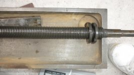
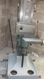
P1290141.jpgP1290140.jpgP1290139.jpgP1290200.jpgP1290185.jpgI finally after a bit of puzzling, removed the vertical table and the x feed screw . The ways are all in as new condition with all the scraping/flaking still present,though not on the vertical column.
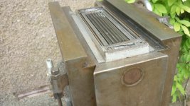
I removed the little plate on top of the saddle and found two very long wicks all gunged up with what maybe grease but im not sure as its not been used for a long while as far as i know. Are the wicks too long, should i clean them with kerosene or something without taking them out ??
Does the screw look very worn?? (a few pictures attached ,either end and the middle.)
Can`t really see the nut as its still gunged up with chips and oily grease.
Bob


Back
Top