What's new
What's new

Cleaning bellows

ole.steen

Hot Rolled
Joined
Jun 11, 2002
Location
Oslo, Norway
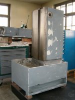
I am in the process of restoring a Schaublin 22 mill, and the whole machine is really dirty with a caked mix of sharp chips and solidified coolant residue. The coolant layer is greenish in color, I have a feeling it might be one of those transparent, non- oil based formulas.

The Y-axis bellows is of the average black fabric type, and has got its share of goo. Do any of you know which solvents will ruin the bellows, and which are reasoably safe? What kind of glue is normally used to make these things?

Ole
 
I had them in a strong solution of industrial soap for aday or so You could use washing powder to probably
On a Deckel if they are damaged i replace them For a schaublin OTOH they are much more expencive so you could try salvage them

Peter from holland
 
Thanks Peter, I'll try a water/ soap based strategy first, then. Yes, the Schaublin parts certainly come at a price, and apart from being dirty the bellows are in good shape.

ole
 
Hi, how's the rebuilding of the Schaublin 22 milling machine going?
I restored one, too... completly dismantled, some parts dropped, some added, cleaning and new colour. Always odd how all the chips and dirt get in complete closed areas. Sometimes I was close to toss the whole thing in the garbage...
 
Hi!

Current status:

222.jpg


221.jpg


The project was dormant for some months before I pulled myself together in november and got going again. I am pretty satisfied with the result so far. I am in the process of painting the electrical cabinet, motor and coolant tank. I still have a lot of road to cover, as I am planning to rewire everything and install a new Mitsubishi PLC instead of the relay logic.

Ole
 
I still have a lot of road to cover, as I am planning to rewire everything and install a new Mitsubishi PLC instead of the relay logic.

Ole


How much logic is there in a machine like this ????
For every motor and direction of a motor you need a contactor anyway

looks like a really decent job so far

Peter from Holland
 
Good status your at now. Motors and feed gear already done. Looks like a nice job. I bet your machine will be great when finished. Mine looked almost the same, at this point it only could get better. Did you already finish the spindle head with the gearbox? This one's fun... alot of wheels.
 

Attachments

  • HPIM1888.jpg
    HPIM1888.jpg
    48.9 KB · Views: 424
Peter:
The relay logic controls feed speed and direction, rapid feed direction, spindle speed and direction, spindle and feed brakes and coolant pump. The feed and rapid feeds are programmable. There is a column of six switches each for the X and Z directions, and three slots where you can set cam pegs operating as "programmable endstops" with different function. One switch will reverse feed direction, while another will engage rapid feed and so forth. The relay logic cards seem to be unreliable, in my machine they have been exchanged for a PLC already, but it is old, and not PC programmable. In my friend Trond's machine there were signs of extensive bending and filing of relay contacts, but still very unreliable function.

I am uncertain if I will implement all the original functions in my rebuild, but at least I need endstops.

BugDS: I have not done the spindle gearbox yet. Mine is the oilbath variety (later machines were grease lubed), and there is rather extensive gear damage and bodged repairs. The gearbox oil pump has been omitted, and needs to be rebuilt or reconstructed. I am contemplating a simplified rebuild with less changegears and a VFD.

Ole
 
I omitted the X and Z columns with the feed switches and put a DRO at those places. Sad about your gear damage, whats the problem exactly? Its important to change spindle speeds carefully and be sure all gears are in contact. I accustomed turning the spindle by hand a bit to be sure the flow is ok. I witnessed hastily Schaublin22 operators... shifting.., gear only half engaged, motor on, ... BOOOM...
Is your work spindle ok? I made a new one to use a power draw bar for automatic tool clamping. I have two spare, the original one with manual pull rod (steep taper size 40) and a not finished pre-machined one for automatic tool clamping.
On my machine i exchanged the 1.1/1.5 kW main motor to a 3 kW one with a VFD. Spindle now turns with 4 to 4000 rpm. Start/stop and instant reverse with a foot pedal. Neat for threadcutting.
 
I bought the machine at an auction in Denmark. It looked like this:
4a29ccb32Dcf322D4ae92D9dd12Da7abd0cbbd42IMG5F7165.jpg


The lower part of the motor pinion was crashed at some point. A repair was done by cutting off the end of the pinion with an angle grinder, moving the pinion further out on the motor axle, thereby omitting the first gear change and the oil pump. At this stage it seems that it was used only for horizontal milling, thereby keeping the lubrication going without the pump. I think it was decommisioned when the spindle bearings gave up. It has SK 30 spindle, and I have a lot of 30 size tooling. I have bought new spindle bearings, they are not installed yet.

The DRO in place of the camracks seems to be a good idea. What do you use for endstops? Have you kept all the changegears functional?

Ole
 
The design of the machine is interesting, since it is really a mix between knee and ram-type milling machines.

There's a real knee, but no "y" movement on it.

And then unlike most knee-type milling machines, machine stands on a big base wich probably limits the travel on "z". That construction is less limiting on ram-type toolroom machines, since one can clamp big parts on the carriage instead of the table.

Since the feed motor is obviously bolted on the side of the knee and the spindle motor is where it is, the machine body is probably totally empty, so what's the purpose of that big base and why they choosed that route puzzles me a bit...

Any suggestions ?

Speaking of that, considering the small volume allowed, the spindle gearbox must be a very interesting piece. Any chance to have several pictures, even if damaged ?
 
Ahh yea, angle grinder repairing is always a pleasure to see. I think to remeber your machine seeing somewhere in the internet some years ago, bellow hanging down and some round clamping device installed on the table. My machine looked almost the same as arrived.

All my chagegears work. Maybe your gearbox looks the same as mine wich is grease lubed. Perhaps no oil pump needed? My machine is from 1974.

The machine body is empty. Behind the electrical cabinet is huge space to store all your gold bars. Only the central lubing device behind the company nameplate.
 

Attachments

  • Schaublin22.jpg
    Schaublin22.jpg
    70.7 KB · Views: 852
  • Gears1.jpg
    Gears1.jpg
    71.4 KB · Views: 648
  • Gears2.jpg
    Gears2.jpg
    45 KB · Views: 382
  • Schaublin 22.jpg
    Schaublin 22.jpg
    52.5 KB · Views: 902
Seeing your pictures, I'm a bit more confused yet about the general layout of the machine.

The "z" handwheel on the front of the machine would suggest the "normal" place of the operator is here, but then there's the "y" handwheel on the left side...

And to balance it all, the spindle gearbox levers are on the opposite side, on the back ot the head !
 
Are there two sets of ring and pinion gears? They don't appear in BugDS's photos. I wonder why the motor isn't co-axial with the transmission like on the oerlikon ub2. Or is it?
 
The motor, spindle and gear axes are all in the same direction, no angled gears. The operator stands over to the left like on the Schaublin 13, but has to step over to the right to change spindle speeds. The z- axis travel is 475mm, much more than you would expect. There is a steadying boom for horizontal milling arbors, but here it can also be used for angles in-between horizontal and vertical. I would guess that the original designer planned to stuff all the electrical parts into the hole in the column, and added the cabinet when he ran out of space.

BugDS: Tell me about your endstops!

Ole
 
The z- axis travel is 475mm, much more than you would expect.

Yes Ole, but travel is not everything.
I can think of numerous occasions when one need more clearance than travel.

I remember a bolt circle I had to drill at the end of my Deckel FP3 ram. At the time, I clamped the ram on the x carriage in lieu of the table of my FP1, and worked with the vertical spindle.
I have hard time figuring out how I would handle the same job (with such a long and heavy part on the 22).

Universal knee-type machines allows to tilt the head around the "y" axis and to use the vertical spindle in horizontal mode, taking advantage of the table length but that doesn't seem to be the case on the Schaublin.

The motor, spindle and gear axes are all in the same direction, no angled gears.

So no reduction of any sort. What is the speed of the motor, and the speed range at the spindle ?
Most of the machines I know have a reduction stage between the motor and the primary arbor of the gearbox.
The cog on the motor is probably pretty small isn't it ?
 
I have a cinematic diagram in my manual, but I need to scan it first. I have this ready:
s22gearsmall.jpg


T: Of course you are right about clearance and travel. On a FP1 type mill you can take off the table and bolt on anything, nearly no size limit.

Ole
 
Curious design indeed.....
Not too crazy about having the spindle offset from the "Y" axis dovetail.
Would impart torque to the dovetail in its short direction making it want to twist....Not so good for plunge milling or heavy drilling i would guess.....
Also lots of potential heat all in one spot...motor, gearbox and spindle...wonder how the growth of the housing affects spindle fit and position accuracy.

Ole.,BugDS
Nice work on your rebuilds by the looks ....Thanks for sharing the details.

Cheers Ross


Back
Top