What's new
What's new

Correct offset for Y-axis handwheel on a 1964 Deckel FP2 mill

ballen

Diamond
Joined
Sep 25, 2011
Location
Garbsen, Germany
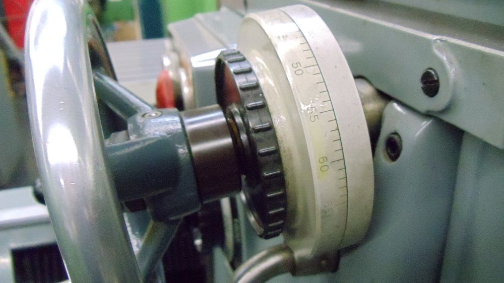
The Y-axis handwheel on my mill looks like this:

attachment.php


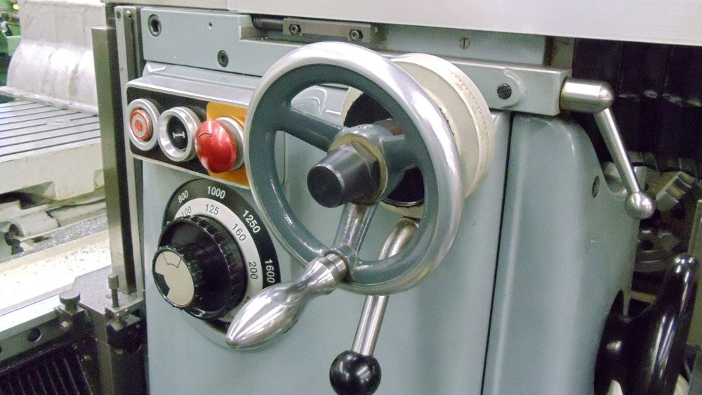
I'm replacing it with one that has a handle, in the same style as X and Z. Since there is a Y power-feed, I am using a 140mm diameter "safety handwheel" which free-wheels unless one pulls it to engage.

attachment.php


In this photo, I have just slid the new handwheel over the shaft but NOT installed it. To install it I need to drill a radial hole the the desired location on the shaft.

Now I am getting to my question. When I mount this new handwheel, I have a choice. I can include the spacer piece (red arrow). Or I can remove the spacer and mount the handwheel closer to the graduated dial. Or I can make a spacer piece that is thinner.

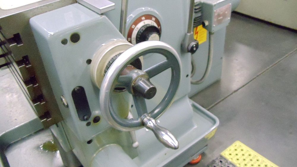
My inclination is to do this WITHOUT the spacer and to make the handwheel as close as possible to the body of the mill. But my question is, what does this look like on machines where this handwheel is standard equipment on Y? Could someone make a photo and post it, so I can see if / what offset is provided?

Cheers,
Bruce
 
Slightly off topic, but if anyone is curious, the rotating handles look like this inside:

attachment.php


They consist of a ground steel shaft inside a very smooth bore aluminum handle: that interface is the bearing. The shaft is retained by two split loops of wire.

This handle had a lot of friction when it rotated, which was easily fixed by cleaning. To disassemble, clamp the handle in a vise with wooden jaws, and use a slide hammer to extract the shaft with split loops.
 
Ill post a picture when I get home. Mine had the new style handwheel installed by Deckel when they rebuilt it.


Verzonden vanaf mijn iPhone met Tapatalk
 
Seems like mine has a shorter shaft. See pictures. Its mounted close to the dial.
If you need different pics, just ask.

Greetings,

Peter

c99947441fadac3e46a4223628bdf688.jpg
d3b6a0fd80a90dcfee777f442d6a0f3e.jpg


Verzonden vanaf mijn iPhone met Tapatalk
 
Peter has it.....
Stationary part that is taper pinned to the shaft is hard up against the step of the threads for the dial locking ring.
Photo showing 2and gen handwheel ...Not correct for your machine , but looks (IMO) better than the squared style that came with the last gen manual machines....
Rounded edges and sculpted handles that are polished steel....

Correct would be the handwheels that have the freewheeling single arm that carries a spring loaded plunger/handle. Plunger is pushed to engage holes on the rim of the handwheel..
My preference as they are easier to use for small moves, in that the handle rim is always engaged so to move all one needs to do is grasp the wheel rim and move...no pushing or pulling
needed

DSC01724_zpsoyibqhi1.jpg


DSC01723_zpsg8st8xbq.jpg


DSC01725_zps9a0ibj7c.jpg


Cheers Ross
 
Dear Peter, Dear Ross,

Thanks for the photos, that's just what I wanted to see! I'll get rid of the spacer and shorten the shaft to reproduce the factory setup that you show.

Ross, I too would prefer the other style of handle. But since my machine came with the aluminium ones, I am going to stick with those, because I don't want a mixture of styles. I personally prefer the feel of the "cylindrical" aluminium hand grips to feel of the "sculptured" steel ones, although I agree that the steel ones look better.

There is one clear advantage of the aluminium hand wheels: they don't rust. Of course in a shop environment where ones hands always have lubrication oil, WD-40, cutting oil and grease on them, this might not matter. But I have heard that some people have hands that will rust steel very fast. So for them it might matter.

Thanks again!

Cheers,
Bruce

PS: Ross I believe that the correct retainer is NOT a taper pin but a split pin. It certainly makes it easier to remove the handles without invoking any cuss words.

PPS: Ross, what's the diameter of the Z-handwheel? My machine currently has 140mm for Y, 160mm for X and 160mm for Z. But I have been offered a 200mm diameter handwheel for Z. Should I take it?
 
Bruce....Can only say that all the handwheels i own use taper pins....but they are not driven in hard, so removal is pretty easy...Maybe mine got changed.


Handwheels pictured (early FP3) has 200 mm "Z" handwheel
160mm "X" axis handwheel and
140mm "Y"

However think the FP3 is slightly taller between the "X" handwheel and the "Z", so the larger wheel on the "Z" is not a problem...
On the "3" the center to center is about 11.5" or so between "X" and "Z"

Cheers Ross
 
I just came across this thread again, and realised that I left it dangling, so am closing it out now.

In the end I fitted a 200mm handwheel to the Z axis of my second-generation 1964 FP2. Factory standard was 180, but I thought that the extra leverage would be nice to have. It fits nicely, although if I lower the Z to the very bottom of the travel, the bottom of the wheel is just a hair away from touching the chip pan. In practice that's a non-issue since I am rarely at the bottom of the travel, and when I am, it's usually because I power-fed down there to get clearance at the top for setup, and power-feed my way back up.


Back
Top