What's new
What's new

Deckel FP1 Grease Removal

Alan

Cast Iron
Joined
Nov 28, 2002
Location
Perth, Australia
Having acquired an FP1 serial # 37187 I find all the slideways and hence the plumbing have at some point been lubricated / filled with grease, how best to remove / clean this considering the small passageways. According to info available the carriage way is the same as fitted to the dial model FP1, there is no access from the top of the vertical slide to the oil gallery area. Thanks for any pointers. Alan.
 
Hi Alan,

Welcome to the group! There is good news and bad news.

The bad news is that you have many hours of work ahead of you. You'll probably need a small lathe to make pullers and bits, a crane or hoist for lifting heavy parts, and patience.

The good news is that there are many people here who have gone through this themselves, and who will give you good advice. If you post pictures and ask questions, you'll get detailed answers about what order to disassemble things, and what to look for.

Other good news: these machines are incredibly robust and can withstand a lot of abuse, so when you are finished cleaning out the grease and getting the lubrication working properly, the machine will probably work very well.

I suggest you start by reading through my thread (which is for an FP2) here:
https://www.practicalmachinist.com/...cal-table-support-tear-down-reassembly-277534

In it, you'll find links to reports from people who have done similar tear-downs for an FP1.

I also suggest you post a few photos of your "new" machine. That will help get the attention of the most experienced people here, who have worked on many of these machines, including ones identical to yours.

Cheers,
Bruce
 
Hi Bruce, thanks for the response and your link, very informative. Must remember, photos or it didn't happen, I have included some of restoring the FP1 dials which are satin chrome plated I think, the coating was lifting and was a bit of a mess, so took a very light skimming pass to get the plating off and then bead blasted with Ballotini impact spheres using a hand blaster used in engraving / etching glass, the finish is very near to original look and it was done about 10 years ago. The skim pass did reduce the lines / numbers slightly, but with some engravers wax pencil applied they are quite readable. Thanks, Alan
 

Attachments

  • blast.jpg
    blast.jpg
    98.4 KB · Views: 154
  • deck1.jpg
    deck1.jpg
    93.4 KB · Views: 185
  • gearbox.jpg
    gearbox.jpg
    92.6 KB · Views: 172
  • dial.jpg
    dial.jpg
    90.1 KB · Views: 168
  • screw.jpg
    screw.jpg
    86.7 KB · Views: 168
Having acquired an FP1 serial # 37187 I find all the slideways and hence the plumbing have at some point been lubricated / filled with grease, how best to remove / clean this considering the small passageways. According to info available the carriage way is the same as fitted to the dial model FP1, there is no access from the top of the vertical slide to the oil gallery area.

Thanks for the photos. I'd suggest a couple of shots of the overall machine, just to help identify the exact model/variant.

Coming back to your question above, have a look at this thread (which is linked from the previous thread that I pointed you to):

FP1 Notes on cleaning and disassembly

and in particular at post #11:

FP1 Notes on cleaning and disassembly

This shows how the internal oil distribution system works in the support and how to clean the long passages. I think you remove the plugs from both ends (drill threaded hole, pull with slide hammer) and then drive the plugs for the cross passages into the main passage, where they can be removed from the ends.

The guy who has that FP1 (Bill) is in Australia, but on the opposite coast from you, so can't easily "drop by" to give you some tips.
 
Hi Bruce, thanks for linking the post from Bill in Oz its most useful, same situation I'm in so I can see a busy week ahead. Will post some photos when machine back together and resembling an FP1 now its a bit like a scarecrow, most things off. Thanks, Alan
 
Thanks for linking the post from Bill in Oz its most useful, same situation I'm in

Glad to help. The "search" function at the top of this page is very very useful. I have found that a few hours of searching and reading have saved me much more than a few hours in lost time, effort, and mistakes. Once you know exactly how everything fits together the work goes much faster and is a lot less stressful.

PS: there may be some sort of oil distribution tube inside that cross channel, so take care not to damage that when you drill out/pull the plugs from the end.
 
I would like to say a big thank you to all who have assisted in this process of grease removal and the previously posted articles on the subject, I am re assembling the machine now but have a question, how to adjust the Z feed shaft selector yolk stops, the 2 pins, photo attached.

When finished will post additional photos and some observations made along the way. Thanks, Alan.
 

Attachments

  • saddle stops.jpg
    saddle stops.jpg
    95.7 KB · Views: 84
I am re assembling the machine now but have a question, how to adjust the Z feed shaft selector yolk stops, the 2 pins, photo attached.

On my machine I did not need to readjust these stops, because they were not adjustable, they were "fixed in place" by the taper pin locations.

The shaft selector has three positions: up, neutral and down. I think you only need to ensure that you engage the shift dogs fully at both ends, and are well-centered in between in the neutral position.

Not sure if this answers your question -- what do you need to adjust or fix/locate?
 
Hi Bruce, the rebuild process indicates that at least the bottom stop pin has been beaten on, hence the bottom drive dog is not fully engaging, only about 75 - 80% with the fixed / pinned portion on the shaft. I have reset the drive shaft brass bushings in the saddle and pinion / bevel gear clearance is running about 5 thou and all turns smoothly. I was just checking / contemplating if any adjustment is available / required before closing up and putting the saddle back on. Thanks, Alan.
 
I was just checking / contemplating if any adjustment is available / required before closing up and putting the saddle back on.

On the FP2, where I have direct knowledge, I don't think there are corresponding stop pins. So you might want to wait from comments from someone who has an FP1 and can speak from actual experience.

Since you have moved bushings and adjusted gear clearances, I think you should be cautious. Before buttoning it up and lifting the saddle back into place, I suggest that you reinstall the shifting lever into the saddle and CHECK that the lever correctly switches both X and Z clutches. It might be a bit uncomfortable to get the lever in there with the saddle sitting on a table, but it beats having to pull it off and open it up later because the clutches are not switching properly.

Bottom line: check that it works right BEFORE you close and reinstall the saddle.
 
Hi Bruce, thanks, yes it was all together, sans backplate when I noticed a bit more clearance than I thought was necessary, so in the end a bit of fettling on the end of the stop pin has mostly resolved it.
Agree the pins look factory set, not to be touched again, until someone has been there before and then any base line reference is lost, one of the joys of getting used machinery.
Thanks for your help. Alan.
 
Well after many weeks of cleaning and other repairs the FP1 is a goer. I would like to thank all for their assistance during this process and the availability of knowledge shared on this site, much appreciated.

As mentioned earlier my machine which had been in storage for about 10 years since purchase was found to not only have grease on the oil galleries but packed into the gearbox's also, probably to hide many past sins, which I discovered were plenty. The grese clearing process was pretty much as detailed in a number of posts, thanks Bruce for pointing me in the right direction, I drilled the gallery plugs M4 and withdrew them rather than knock through into the gallery as unsure of the height, but would have been fine. Used short M4 grub screws to fill the plug hole and reused with some Loctite 515 to seal the thread.
The felt used for the gallery restrictors I found was not the stuff I had which is known as "piano" felt which is quite dense and really did restrict passage of oil to nearly nothing, instead after having a supplier look at an original felt it is what is termed B grade felt and lets oil pass at a low rate and thanks to Bill Fisher's diagrams correct installation was easy.

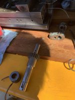
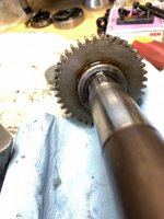
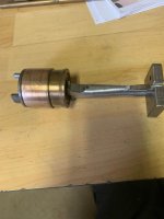
The X & Z feed power drive shaft as per photo had a hard life, so put is a plug, JB weld and cross drilled another tapered hole, ended up using 3/16 pins, I think #2 throughout as that was the reamer I had with pins provided by Bob another forum member locally, they are only slightly larger than the Metric 4 ones used originally. Various bearing pullers and pushers were used, some depicted in the photos and some mods were made,the last photo is of the hand feed Z axis bevel gear, a collar was made and loctited in place to limit any further growth.
The 4th photo is the idler shaft, took some considerable effort for someone to withdraw it while the set screw was in place.

An illuminating couple of weeks, made worthwhile as the Deckel was originally a quality machine and worth the effort to bring it back to operation. There will be several posts to account for the number of photos. Thanks, Alan.
 

Attachments

  • 1.jpg
    1.jpg
    97 KB · Views: 70
  • 1.5.jpg
    1.5.jpg
    93.8 KB · Views: 85
  • 2.jpg
    2.jpg
    97.1 KB · Views: 66
  • 4.jpg
    4.jpg
    92.1 KB · Views: 66
  • 15.jpg
    15.jpg
    85.8 KB · Views: 61
Continuation,
photo 1 the power feed shaft previous drilling attempts, filled and cross drilled another taper pin hole.
Photo 2 milled a spanner flat on the end of the Z screw shaft for ease of holding.
Photo 3 added an oil zerk to the Z feed handwheel shaft as unsure of the oil flow from the idler gear shaft to migrate to the bushing near the handwheel, benefit now is oil can be back flowed into the lower gearbox.
Photo 4 drilled an oil hole in the skirt of the Z screw thrust washer bushing to add oil as req.
Photo 5 Elesa H20 sight glass installed, while the viewing aperture is slightly smaller than the original at least its clear and easily viewable.
 

Attachments

  • 3.jpg
    3.jpg
    96.5 KB · Views: 54
  • 8.jpg
    8.jpg
    78.3 KB · Views: 45
  • 6.jpg
    6.jpg
    93.8 KB · Views: 50
  • 9.jpg
    9.jpg
    91.8 KB · Views: 96
  • 13.jpg
    13.jpg
    92 KB · Views: 46
Continuation,
photo 1 collar on Z handwheel drive shaft bevel gear
photo 2 drive gear for vertical spindle horizontal shaft, drive key appeared to be undersize by around 1mm and chewed on side of gear
photo 3 drive gear
photo 4 as I dont intend to use suds, pump removed, frees up some space and makes access to sump easier
photo 5 to remove X feed bushing on LHS of saddle, viewed from front, used 2 legs from a Toledo micro bearing puller, small enough to fit inside bushing. Alan.
 

Attachments

  • 21.jpg
    21.jpg
    90.4 KB · Views: 42
  • 17.jpg
    17.jpg
    86.6 KB · Views: 42
  • 18.jpg
    18.jpg
    91 KB · Views: 37
  • 20.jpg
    20.jpg
    86.7 KB · Views: 43
  • 16.jpg
    16.jpg
    86.8 KB · Views: 44
Dear Alan,

well done! Smart to rescue the cracked bevel gear, since it's on the hand crank it will probably be fine for the next century like that.

What's the collar with the two copper tubes coming from it, second-to-last photo in this post?
https://www.practicalmachinist.com/...deckel-fp1-grease-removal-381081/#post3643110

Cheers,
Bruce

PS: would enjoy a photo of the entire machine -- are you fitting a DRO to it?
 
Hi Bruce,
Thanks, the brass tubes are from the collector at the top of the idler shaft, have notated on the attached print out from someone, hope they don't mind me posting here. When that shaft was graunched out the original tubes and collector ring were obviously damaged, so this was their replacement, one drips oil into the Z axis handwheel shaft, hence my putting and oil nipple into that shaft incase the drips missed the hole, hard to line up when assembled.

Yes plan to put a DRO on it and will post some photo's when all finished, just running in and making the small adjustments for the new bearings. Thanks, Alan.
 

Attachments

  • 23.jpg
    23.jpg
    91.4 KB · Views: 56


Back
Top