What's new
What's new

Deckel FP1 High Speed Head

Alan

Cast Iron
Joined
Nov 28, 2002
Location
Perth, Australia
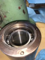
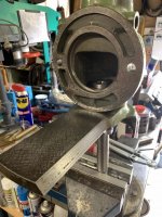
I'm in the process of giving the high speed head some much needed attention, trying to remove the bottom retaining ring on the spindle, unsure if left or right hand thread, but so far very reluctant to move, any advise appreciated.The collet size is 16mm.
Thanks Alan
 

Attachments

  • drive3.jpg
    drive3.jpg
    90.3 KB · Views: 138
  • Retainer.jpg
    Retainer.jpg
    17.4 KB · Views: 132
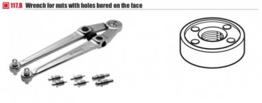
Just to provide some feedback, the nut / retaining ring at the bottom of the quill, is Left hand thread, the 2 existing pin spanner holes were not in good shape, had been attached with a pin punch, so drilled 2 additional holes and made a 3 hole pin spanner using the best holes. After a heat cycle and soaking the nut came off, but quite a bit of force still required. This spindle has many similarities with the Vertical head, I will post details and some photos when it back together and running. Thanks, Alan.
 
Further to the above, have overhauled the head mainly for bearing issues, the originals were ********* open cage, two 6008 at the top and two 6006 in the spindle, I have replaced all with NSK ZZ sealed units as very little else in the assembly needs much lubrication which can be applied by other means. The unit ram I have has been shortned, now a stumpy at some time and thanks to a posting by Ross (AgfaGTA) 07-02-18 explains why this may have happened, the only downside is that the unit serial number went with the cut off bit.
stumpy2.jpg

The electric motor is standard 0.55Kw and will be run off a VFD
HSH25.jpg
howerer the drive pulley had the set screw pulled out, so a sleeve was loctited on and tapped for new set screw rather than cut a new keyway, seems to be ok.
HS5.jpg
The upper bearing module consists of the 2 bearings, spacer and 1 Belleville pack, the screwed bearing retainer under the pulley has 3 adjustment screws in a Tribach arrangement, presumably to tweak the seating of the bearing, this arrangement is the same as on the vertical spindle. TBC next post
HS9.jpg
HSH1.5.jpg
 
Continuation:
Most of the locking collars/nuts have a lock screw, so care to undo before removing
HS8.jpg
The spindle unit has two 6006 bearings, spacer, 2 Belliville washer packs together and 2 locknuts at the top, the outer 1 is standard thread, but the inner 1 is Left Hand thread, the same for the lower retaining nut which contains the Labyrinth seals. I engraved an aide memoire on those that are left hand thread, not for me but the next person in there. TBC next post
HS7.jpg
HSH 22.jpg
HS3.jpg
 
Continued:
Tools used were pin spanners and I found an adjustable one useful for some of the locknuts, but also had to make some from old flat spanners which is quicker than having to do from scratch
Screen Shot 2020-11-02 at 7.48.36 pm.jpg
HS1.jpg

Another useful tool made was an arbour to hold the unit while adjusting the Belliville packs, its the size used when doing the vertical head and was made from scrap box material with the following dimensions:
overall length 260mm, diameter where it goes into drive 28mm, keyway length 70mm and 2 flats milled on the end to place into a vise or be held with a spanner. In the absence of a serial number the inside of the head casting is included.

HS10.jpg
HS4.jpg
HS11.jpg

After I receive inverter in the next day or so will give it a run to see if I have the Belleville washer settings correct, which I find so far is by feel and noise. Will be continued later. Alan.
 
Update:
Some adjustment work to get the bearings and belliville washers set up, but the major stumbling block now is the quill tension spring pack, I released it on disassembly and I'm having a heck of a problem getting it back in the housing as its wound tightly and its strong, nothing like the vertical spindle spring pack.

Has anyone had any experience with this, any pointers appreciated.
Thanks, Alan.

spring.jpg
 
Alan,

I struggled with this on my machine to. I think I ended up working it into the female/inner side so I didn't have to keep it compressed. Also I think towards then end I used the out side piece to wind up the center. It has been awhile but I think this was how I ended up putting it back together.

Hope this helps,
Nigel
 
Hi Nigel,
Thank you, have managed today to get it back together by making a mandrel out of 20mm shaft turned down to 18mm with a 1.2mm slot to take the inner end of the spring. The end of the shaft was further reduced to 11.9mm over about 8mm and tapped for a 6mm bolt in the end, this reduced section fits into where the shaft would go through the inner housing, the 6mm bolt just holds it in place, but must be loose enough to rotate. Flats on the other end of the shaft for spanner to turn it.

Put spring on shaft and then the inner housing and secure loosely with bolt and place the larger diameter of the shaft just behind the bell housing in vise soft jaws. Hook end of spring into outer slot and carefully wind up spring until it fits inside the inner housing. Wear PPE, if the spring lets go it would tear skin off.
Back off mandrel tension a bit, undo bolt and withdraw, put outer housing on picking up the spring inner hook, job finished except for adjusting tension when in place. Thanks, Alan.

spring1.jpg spring2.jpg spring3.jpg spring4.jpg
 
Last edited:
That's a nice tool.

When you can't get something apart or back together, it's worth making tools for that. I have an entire shoe-box crammed with one-off tools which I made for the disassembly, repair and reassembly of my FP2 and its accessories. The most recent were this "poor man's collet" for unscrewing the retaining bezels of the main on/off control switches and a wrench (actually a 55mm insert for a die holder) for tightening a compression/retaining nut on the horizontal spindle.


attachment.php


attachment.php


attachment.php
 
Hi Bruce, yes mate have made more special / specific tools for this machine than anything else. That poor man's collet is a good idea, thanks.

The shaft I used came from an old industrial photo copier, they have a treasure trove of shafts, rails, screws, pulleys, lenses etc and I've found places give them away, just have to dispose of the remains afterwards. Thanks, Alan.


Back
Top