What's new
What's new

Deckel FP2 Speed & Feed Handle

Jersey John

Stainless
Joined
May 29, 2015
Location
Beccles / Suffolk, United Kingdom
Hi folk ...

Some may know that I've recently acquired a 1965 Deckel FP2. As with all machines of this vintage there are always bits to do. In my case a number of bits!

The Speed & Feed handles have springs inside the barrel of the handle that push a locking plunger down into a recess of the operator side of the machine. My springs were virtually totally ineffective and finding the right way to disassemble the handle and replace the springs was not obvious ... but now sorted :)

Here's the pictures: First the handle, note the rubber oil seal ... second picture the handle in bits lastly what's behind the handle.
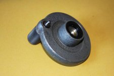

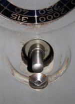
Parts-Handle001.jpg

Parts-Handle002.jpg

IMG_0256m.jpg

IMG_0250m2.jpg

To actually get the handle barrel apart you need to drive the plunger pin out of the barrel from the top of the handle with a drift or press (a lot of pressure is required!)

Hope thses notes help someone ...

... and thanks to those that have helped me too! (Ross & Bruce) ;)

John :typing:
 
Believe what i did to get them apart (thanks for your pictures to remind me) was to make a spacer ring...Id bored to clear the step on the handle casting...and the OD somewhat larger than the OD of the knob....
I sawed the ring apart to make two "C" shaped sections...Slide the C's under the knob and pressed the assembly apart.
But i think its OK to just push against the casting...won't damage the spring or the part if your careful.

Also made a riser (cylindrical) with clearance hole through with the ends and faced flat to support the casting at the plunger...Hole large enough to allow the plunger to pass.

On mine the removal of the taper pin that retained the crank was difficult....As i recall, the cross hole was already somewhat hurt, and after removal was pretty rough....needed a bit of welding and a
new cross hole, reamed to fit a new taper pin.

Cheers Ross
 
Now as i recall, this machine is missing the original push buttons....
Not sure that your removal of the crank has to do with the button replacement/repair...but for sure now is the time to address this issue as removal of the operators side panel requires removal of the
speed and feed dials....

The crank detent seats (where the plunger engages) are retaining bolts for that panel....Can't remember, but i believe that there are also bolts from behind.
Open the door on the non operators side. (unscrew the knob) then remove the sheet metal plate that holds the clips for the oil guns....will reveal bolts that pass through to hold the panel on.

Need to remove the rapid feed lever and coolant pump knob as well. Be aware that there is a locating slotted screw through the rapid feed lever in addition to the clamp pinch bolt...
Cheers Ross
 
On mine the removal of the taper pin that retained the crank was difficult....As i recall, the cross hole was already somewhat hurt, and after removal was pretty rough....needed a bit of welding and a new cross hole, reamed to fit a new taper pin.

Cheers Ross

Thanks for your input Ross, as always greatly appreciated.

Ha! ... I expected my taper pin to be difficult too ... sadly not ... didn't even drift it out with force ... It actually shot across the shop floor :eek:

John :typing: :cheers:
 
John, congratulations on getting this off without doing damage! Thanks also for documenting it with photos.

Ross, you said:

On mine the removal of the taper pin that retained the crank was difficult....

I have never needed to remove the speed changing cranks to fix something. But I have made some feeble efforts to get them off, which failed completely, because I think the taper pins are very much corroded/bent in place, like what you describe. What's more, I don't think there is any clearance to get a drill in there to drill them out. And I'm afraid if I just go at them with a bigger hammer, I'll damage the cranks or what's behind them, or bend the shafts. Any suggestions? One of these days I am going to want to repaint the sides, and the only reasonable way is to get the cranks off first.

[I'll put some penetrating oil on them every time I think of it, for the next few weeks. Maybe that will help a bit. Anyway, it can't hurt.]

Cheers,
Bruce
 
Last edited:
Now as i recall, this machine is missing the original push buttons....
Not sure that your removal of the crank has to do with the button replacement/repair...but for sure now is the time to address this issue as removal of the operators side panel requires removal of the
speed and feed dials....

The crank detent seats (where the plunger engages) are retaining bolts for that panel....Can't remember, but i believe that there are also bolts from behind.
Open the door on the non operators side. (unscrew the knob) then remove the sheet metal plate that holds the clips for the oil guns....will reveal bolts that pass through to hold the panel on.

Need to remove the rapid feed lever and coolant pump knob as well. Be aware that there is a locating slotted screw through the rapid feed lever in addition to the clamp pinch bolt...
Cheers Ross

The replacement of the switch gear is on going too ... but I don't need to remove the side panel ;) ... The original cable is still in place so I took the Oil Gun panel off on and just eased a little more cable up through the cabinet. There is enough wire to feed through the two holes and connect up to the switches.

I got two switches from Franz Singer for U$20.00 and although the original switches may not have the best of history the ones I've received seem sturdy enough so I'm going to give it a go, nothing to loose as the refit is minutes.

I also was worried about grease being injected through the nipples for the Z axis, Stradbash suggested I try pushing oil through "Just in case" ... and within seconds I had oil running down the vertical ways and on the lead screw so I'm guessing that maybe the "Machinery seller" had just put a quick squirt of grease through the nipples before selling.

The machine came from an industrial company (Along with an FP3L) that's just closed down and has been with them for 49 years so I'm ever hopeful that their operators did operate it as per the book and put oil in the all right places. I know it’s an assumption but I feel fairly good about it and my findings so far especially as I have all the original manuals and brochures of the time.


Cheers John :typing:
 
Bruce:
My technique for small taper pins like these is to try and start the pin moving using a very short drift....You know, you take a longer pin punch and after it bent trying
to move something, you shorten it way back...maybe 3/16" long after reworking...that will give better control at
staying on the taper pin...and more of the energy of striking the punch will be delivered to the pin....
Once it moves usually you can then easily drift the pin out using a longer punch....

Some discussion here years back on getting these pins out, and at last one member suggested making a "pusher" to push the pins free....Not tried this, but worth thinking about...
Suggested something like a "C" clamp with the screw being formed at the end as a pin punch....The "C" frame to bridge the casting, and having a hole or notch in the anvil to allow the pin to pass through
on its was out....

Would eliminate the jarring forces that hammering create, but i am doubtful that a screw will make the sort of force that a hammer blow creates, and keeping the end of a rotating screw centered on the pin seems difficult.
Perhaps a two piece shaft...a screw acting on a guided pusher that in turn pushes out the taper pin.....Seems like a lot of work.

As to the hammering...shafts are pretty robust and well supported....would take some pretty severe blows to cause a problem i believe....

Cheers Ross
 
Ross, good idea about the very short drift. I think I even have a damaged drift somewhere that I can grind/shorten/convert for this purpose. Also reassuring that the shaft is pretty solid. So next time I try this I'll ignore the ladies ball-peen hammer and use the short-handled 5kg sledge hammer instead! Cheers, Bruce
 
I needed to replace two broken springs in this handle and another one like it:

attachment.php


At first, I tried to punch apart the handles as shown in the first post of this thread, but the "interference fit" was much too tight. So here is my solution based on Ross' comment. I turned two parts. The first one is a steel post about 40mm long, 30mm diameter, with a 10.2mm hole down the middle:

attachment.php


The larger OD at one end is not necessary, but was there on the scrap that I used. The second part is aluminium, 30mm OD, 45mm long. It is bored 23mm ID, 25mm deep, then drilled through 5mm for a 5mm ground dowel pressure pin. (Needs to be < 6mm, so in the Imperial world use 7/32").

attachment.php


attachment.php


Here is how you use them together. The aluminium part supports the pressure pin and guides it, the steel part supports the backside of the handle and provides a place for the locking pin of the handle mechanism to come out.

attachment.php


The hydraulic vise generates about 40,000 Newtons (4 metric tons, 9000 lbs) of force, and it was all needed to get these apart. There was an impressive "crack" when it broke free, Use a short pressure pin to get it moving -- you can replace it with a longer one to completely drive out the locking pin. Wear safety glasses, just to avoid having a piece of broken 5mm steel pin fired into your eyeball.

Last point: the spring inside is made from 0.8mm wire, has an OD of 8.5mm, is 26mm long, and has 9 turns, of which 2 are "lost" at the ends and 7 are "active".
 
Last edited:


Back
Top