What's new
What's new

Find FP4NC Transmission Drawings

smith730

Plastic
Joined
Jan 13, 2015
Location
CB, South Korea
I have the body of an FP4NC machine. I'd like to take the time to get this equipment working again.

First of all, I think I need to know exactly how the transmission works.

I want to know how the FP4NC transmission works, as shown in the picture. I would appreciate it if you could share any help or drawings for transmission device materials.

유압변속장치.jpg
 
Last edited:
Sorry, no parts book here at home (lock down).
But i can tell you how the gearbox works....
There are three snifter shafts that move the gears within the box.
Those shift shafts have a drum on each with a series of logs on the surface of each drum.
Each shaft also has micro switches in a carrier that allows the switches to ride on the drum surface and be activated by the lugs on the drum surface.
Believe there are 3 switches on each shaft/drum
Finally there are three small pancake motors at the outboard end of the shafts.

When a gear is selected, the machine simultaneously jogs the spindle using reduced voltage on the drive motor,and releasing the spindle brake....
At the same time power is applied to the shifting motors and they rotate until the proper set of contacts have been made.
Its a logic thing...when the proper set of contacts has been made, the shift motors are stopped and the spindle is started at full speed....
Note: the drive motor is two speed and the correct set of relay contacts are engaged to give the proper output spindle speed....

The jog sequence does 4 jog pulses in one direction then reverses for another 4 pulses, then 4 more in the original direction...all to help the gears mesh.
If the jog sequence does not result in getting all the needed switch contacts made for the selected speed, the machine faults to an emergency stop.

All this shifting is controlled by logic on cards within the large electrical cabinet (PC)

This is a complex system, and it would be difficult to replicate if you are missing much.

Further, if you are planning to shift teh gearbox by hand, be aware that there are no detents on the shift shafts....their position and proper gear mesh is defined by the cam and switch setup.
So to run manually, one would need to make some method of holding the gears in proper mesh for each gear set.

For my money the easiest work around for the gearbox, would be to devise a setup having two speed ranges that you could engage manually (one shift shaft hopefully)
and lock the other shift shafts in place .
Then fit the drive motor with an encoder, and run it using a commercial spindle drive (variable frequency)
The selection of the set gears would be such that you would get good torque over the widest range of speeds ...would need to do some math to find the best combination.

Cheers Ross
 
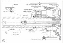
Drawing of D4 FP2-NC. Should be about the same, as D4 FP4-NC, only a bit smaller.
DSC_0113.jpg

Belt drive is top right, goes to 3 gears on top shaft. Gear on bottom shaft is moveable, on splines, with that cam motor. Spline shaft is fixed to small gear in low middle. That small gear goes to big gear fixed on top shaft, left side. Bottom left shaft 2 movable spline gears, also with cam motor.

Goes to next drawing, not sure what happens there, probably idler and back gear...
DSC_0114.jpg
 
Dear Ross and DeadMahoDude

Thank you for your detailed explanation.

And I'm sorry. I was not good at attaching a picture file, so I failed to attach a picture.

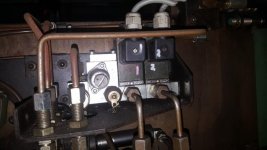
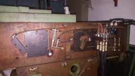
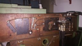
Now I attach a picture of the curious part of my equipment.

I think the machine I have is probably changing the gear position by adjusting the hydraulic valve, but the question is how did this machine choose a complicated gear position with two solenoid valves?

I haven't seen anything like this in other FP4NC manuals or related photos that I've looked at so far.

If anyone knows, please give me some help or explanation.

Best regards

John


KakaoTalk_20200423_014502168.jpgKakaoTalk_20200423_014502517.jpg유압변속장치.jpg
 
Dear Ross and DeadMahoDude
I think the machine I have is probably changing the gear position by adjusting the hydraulic valve, but the question is how did this machine choose a complicated gear position with two solenoid valvesh

It's because you have a Dialog11 2838 FP4NC. Only 2 gear speed ranges 30-about600rpm and about600-5000rpm. The rest is done by Bosch ASM variable frequency drive. Set spindle speed to 50rpm, turn on spindle, you should hear it shift. Stop spindle, set it to 1000rpm and turn it on, it should shift again.

That poor thing looks totally rusty btw. Do you live by the ocean or something?
 
Drawings shown in post 6 and3 are different . The spindle setup on the FP2NC is different form the FP3nc andFP4NC...
But neither set of drawings are correct for the OP's machine....
Those drawings are for the early series of gearboxes for the FP-NC....having electric motor shifting for the gear box with three shifting shafts etc....as i described in post #2.

What the OP has according to the photos posted is the later setup, having but 2 gear ranges, that are hydraulically shifted and using a spindle drive (VFD) to vary the motor and hence the spindle speed within each of the two gear ranges....

Cheers Ross
 
Hi, I have an FP4NC 2838
Here's all the drawings that are in the documentation, a lot appears to be missing though
hope they somewhat help though
photo_2020-04-27_18-11-21.jpgphoto_2020-04-27_18-11-21.jpg
photo_2020-04-27_18-11-50.jpgphoto_2020-04-27_18-12-35.jpgphoto_2020-04-27_18-13-25.jpg
 
Hi, I have an FP4NC 2838
Here's all the drawings that are in the documentation, a lot appears to be missing though
hope they somewhat help though
View attachment 286448View attachment 286448
View attachment 286449View attachment 286450View attachment 286451

Dear Blacktronics
Thanks so much.
I think the drawings you sent me are exactly the same as my equipment.

Thank you again.

If any of you have any helpful data regarding this equipment, please share it with me.
 
Drawings shown in post 6 and3 are different . The spindle setup on the FP2NC is different form the FP3nc andFP4NC...
But neither set of drawings are correct for the OP's machine....
Those drawings are for the early series of gearboxes for the FP-NC....having electric motor shifting for the gear box with three shifting shafts etc....as i described in post #2.

What the OP has according to the photos posted is the later setup, having but 2 gear ranges, that are hydraulically shifted and using a spindle drive (VFD) to vary the motor and hence the spindle speed within each of the two gear ranges....


Dear Ross
Thanks for your advices.
 
It's because you have a Dialog11 2838 FP4NC. Only 2 gear speed ranges 30-about600rpm and about600-5000rpm. The rest is done by Bosch ASM variable frequency drive. Set spindle speed to 50rpm, turn on spindle, you should hear it shift. Stop spindle, set it to 1000rpm and turn it on, it should shift again.

That poor thing looks totally rusty btw. Do you live by the ocean or something?


You are right. my machine is Dialog11 2838 FP4NC.

Thank you so much :D

And......I must have broken your heart by showing you a poorly managed deccel.
I'm sorry.

I accidentally found this machine that was being dismantled to sell it as scrap metal, and I'm so sorry for this equipment that I'm trying to fix again and save it as CNC.

If any of you have any helpful data regarding this equipment, please share it with me.
 
Hi, I'm smith730
Sorry to late reply

I wish to build by New cnc system that it wil consist with newker 1500MCda controller(5axis - 4axis+1 ATC axis) and Yaskawa AC servo pack 1kw.

But now there are only mechanical bodies, and parts such as motors and drivers are in disassembled storage.

With all the wires cut off, it is expected that it will be difficult to rebuild the wiring.


Back
Top