What's new
What's new

FP1 Notes on cleaning and disassembly

Bill Fisher

Aluminum
Joined
Nov 17, 2013
Location
Sydney, Australia
Hello – my first post on this forum.

Recently I purchased a Deckel FP1 (serial no 54490/28) at auction in Melbourne. I was lucky enough to get a twin dial, SK40 version with a plastic door on the coolant pump enclosure, supplied new to Philips in Melbourne in the early 1970s, I believe. Probably was looked after immaculately by Philips, but later passed into some less careful hands.

Anyway, I decided to clean it thoroughly and pull the slides down for inspection and assessment. I quickly discovered that someone had greased the oil lube system fitted to the saddle, and thus began my current saga. The Alan “Wrench” DVD has been a great help here, and I would recommend it to any Deckel owner.

I'm sort of parallel here to ballen's great thread about his FP2 (similar age – similar problems), which revealed to me that the FP1 has some different details. A fair bit of what I have to say is covered on this forum and elsewhere (albeit scattered) so I hope to concentrate some material as well as covering some aspects I have not seen elsewhere.

Photos to follow when I work out how.

Regards,
Bill
 
Hi Bill,

Hello – my first post on this forum.

Welcome! I'm also a newcomer.

I'm sort of parallel here to ballen's great thread about his FP2 (similar age – similar problems), which revealed to me that the FP1 has some different details.

I'll follow your thread as you've been following mine. If you have trouble uploading pictures send me a private message and I'll help you sort it out. I've had lots of practice (:-).

Cheers,
Bruce
 
Hello Bruce. Thanks for the welcome!
I am not sure I can come up to your standard so don't expect too much.

First, a photo of my FP1 at the auction.
1 at auction .jpg 2 IMG_8425.jpg
(By the way, can someone tell me how to rotate these images? Kept looking for how to do it, but no luck.)

Notes on the inside of the coolant pump door suggest early an 1970s purchase date.
3 inside door.jpg

There is a fair bit on info available about taking apart an FP1 (my reading included every FP1 related thread this forum) so I will skim over disassembly of X, Y and Z slides, and show mainly aspects where I needed special tools or more information.

Mostly the cleaning was done with cotton rag and mineral turpentine or kerosene, resorting to acetone only in desperation when trying to shift ancient varnish that was once oil etc.
The ability of fine chips plus oily dirt to pervade every nook and cranny is remarkable, and kept me delving ever further into the disassembly to be sure of a thorough job.

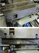
Cleaning proceeded from the top down. The the vertical head was put aside for a later time, and the Y axis slide came apart without dramas, revealing the state of the surfaces.
3b Y slide condition.jpg
Not being experienced in judging slideway wear I presumed that a lot of iron had been worn away at the front, but it turns out to be about 0.001" at the worst part, although that is to the 'plateau' not the full depth of scoring. Still a fair bit, but not as much as I feared. Probably scrapable, but probably not a good place for my very basic (and long unused) skills to be tested.
The screw and nut look good.

The drive and feed gearboxes seem to be free of meal chips so cleaning was limited to mopping out the fine black sludge that accumulates in the sump over time.

Cleaning of the dial assemblies was easy enough, but if you take these apart do be sure to mark the alignment of every single piece as it comes apart, and remember that the aluminium information plates are not positively located in relation to the carrier, so when they pop off you have lost the position unless you marked it first.
Immediately after removing the dial assemblies from the column, mark the relationship of the gears in the dial assembly before they roll out of engagement. Otherwise you are in for some fun working it out from scratch. Refitting of the dial assemblies is a bit fiddly because you have to line up the selector grooves in the gearbox with the shoes of the dial assembly by eye, then 'close the lid' hoping everything will go together. As my dad used to say, you will know how to do the job when you've finished.

Well I seem to be running up to a 5 images per post limit, so will come back another time.
Cheers,
Bill
 
Hi Bill,

Your machine looks cleaner than mine did from the start, especially around the top gear mine had congealed oil that had turned to something more like soap or grease.

Rotate the pictures on your camera or laptop BEFORE you upload them. I typically write my entire entry, marking the locations of photos with numbers (corresponding to the picture number I want). Then at the very end I upload all the photos at once and stick the wiki tags into the correct locations corresponding to the numbers, then erase the numbers.

I wonder if the notes inside the coolant pump door have to do with changes of coolant rather than oil, or is this door also access to the oil change for the cutter spindle and automatic feed gearboxes?

Keep on posting!

Cheers,
Bruce

Bruce,

The 'at auction' photos are obviously before any cleaning, but the others are after cleaning.

Thanks for sharing your prep technique for posts - mine is quite similar with numbers in the draft text indicating which image to use. Re the orientation of photos, all were correct before uploading but some came out sideways, so I will try 'pre-correction' of the orientation if the problem happens again.

You may be right about the dates being for coolant change, although it does say 'oil change', and coolant would normally be added directly into the coolant reservoir at the front. The door gives access to the coolant pump, and the fill and drain points for the feed gearbox.

Back to the cleaning!
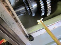
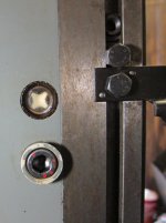
The spindle drive gearbox sight gauge was clouded with brown oil varnish. Cleaning this from the inside is fiddly because you need to reach through the gearbox, past the gears and lower drive shaft, but it can be done.
4b1 drive box sight gauge location.jpg
First you need to remove the white X shaped contrast piece, which can be pulled out with a bent wire.
4b3 sight gauge contrast piece.jpg
Then the brown goo and varnish on the sight gauge was rubbed off (easy to say!) using a wooden stick carved to fit around the gears and shafts, and with a solvent soaked rag on the end.
4b2 carved cleaning stick.jpg
Using double sided tape, the contrast piece was fixed to the end of a wooden dowel and snapped back in place.
4b4 refit contrast piece.jpg
The result is quite acceptable to me. There seems to be a misty deposit on the inner side of the sight gauge, but I hope this will be less evident after oil is added to the box.
4b5 drive box cleaned sight gauge.jpg

The sight gauge for the feed gearbox oil level is practically impossible to access from inside without removing the gearing. Fortunately it is acceptably clean.

Bill
 
Last edited:
Hi Bill,

Well done, I didn't realize that you had opened the drive gearbox. I didn't do that with mine, because after changing the oil I have no trouble seeing the levels, and it appears that all is working OK in there.

As an alternative, you could also pull the sight gauges out from the outside of the machine. However they are a press fit and this will probably destroy them. Replacements can be purchased either from FPS or from Franz Singer Werkzeugmaschinen in Germany. Singer has both the original Deckel parts, that cost ~20 Euros and replacements from ELESA that cost less but are functionally equivalent.

Cheers,
Bruce
 
Bruce,
Thanks for your sight gauge replacement options. I do like to keep originals if possible because they fit in with the character of the machine: the plan does not include a cosmetic restoration (not yet). Also it is much quicker to clean them than remove, wait for items to come from overseas etc, so in general I repair parts or or clean them rather than replacing. At this stage the aim is to get everything clean, particularly the wearing parts, and get the machine to a condition where I can use it, and at that point decide if I want to restore the slideways etc.

Jochem, it's nice to know you are reading this, and I just hope what I show applies to your machine. As I understand it, FP1 design changed progressively over the years.

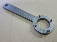
The X slide disassembly followed a well-documented path, the only problem being a pin spanner for the leadscrew nut. A suitable design was posted by Adrian (http://www.practicalmachinist.com/v...abene-mills/removing-x-axis-table-fp1-154889/ post#4) but the design did not suit the resources and materials available to me on the day, so I made up a spanner from 5 mm thick mild steel plate and roll pins. No precision was involved, other than coordinate drilling for the pin holes.
8 X nut removal.jpg
7 X nut spanner.jpg
It worked a treat and did not damage the pin holes, which I suppose is to be expected since the Deckel spanner in the parts list has only two pins.

As received by me, the X leadscrew had about 1 mm (.040") backlash so I was expecting lots of wear, but not this.
9 X nut 1.jpg
10 X nut 2.jpg

Like the Swiss Alps on steroids. The concern was not the worn nut (that was expected) but how was I going to clean all of those bronze bits out of the saddle?

I am also curious about the failure mode that would cause bronze to fragment in this fashion - could corrosion from exposure to coolant be a factor?

The repair plan for the nut is to bore it out to take an internal bronze sleeve, fit the sleeve, then the new internal threads. Plan B is to remove the sleeve and try again. Plan C, buy a new one.
The machine is an inch machine with the X leadscrew thread pitch being 0.1", so I presume the threadfom is Acme, not trapezoidal. Can anyone confirm that?

Regards,
Bill
 
Plan C, buy a new one.
The machine is an inch machine with the X leadscrew thread pitch being 0.1"

Bill, FWIW, I see Singer advertising brand-new inch X leadscrew nuts on Ebay for somewhat more than 100 Euros. No idea what would cause it to fragment like that. Anyway, as long as the leadscrew is in good shape, a new nut will do wonders. Cheers, Bruce
 
Last edited:
Hi Bruce,

I really envy your proximity to Singer! I suppose he is my fallback position for a lot of things, but first I will see what I can get locally, and what I can make.

Alan, you may well be right about the nut wear, but I still find it surprising.


To continue....with the X slide is off the ways were revealed.
Upper X way is nice, with modest wear evenly distributed over the two surfaces, and scraping marks still covering a lot of area. Probably this is because these ways continued to get lubrication - on my FP1 there were no wicks or felt flow-restrictors plugs in the oil galleries feeding the upper X ways. The lower X way surfaces, which would have been starved of lubricant following use of grease, have more wear, and a one prominent score line, but still with a touch of scraping showing in the middle.
11 X slide ways.jpg

The saddle came off without difficulty. A 1/2 ton chain hoist is perfect for this work; light and easy to use, no safety worries, and very good control over lifting and lowering.
A quick look at the back of the saddle shows the bad news with grease lubrication - clogged gallery and oil grooves.
12 Z slide inside.jpg
Despite this, the Z ways show quite evenly distributed wear with scraping marks all over.

So now the game is to clear out all of the grease and wear debris from the saddle.
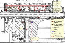
It helps to have an understanding of what's in there, and how to take it apart, so to take you there (hopefully) I will start with a drawing from the Deckel parts manual for the FP1 (twin dial version). The drawing shows a section through the upper part of the saddle, with labels on some of the more important bits, selected for their relevance to later discussion.
13 saddle section labelled.jpg

It is worth noting that the original purpose of this drawing was for identification of parts, and you should not expect such a drawing to be totally accurate. Unlike design drawings, parts drawings need not be to scale, or complete with regard to details. Why does this matter? Well, it matters if you are using the drawing to understand how things work, how to remove parts, what is blocking the removal of a part etc. At one stage of the disassembly, this particular drawing had me wondering due to proportions that could not correspond with reality. Livens up a dull afternoon!

Now that you have digested that, the next drawing shows my conclusions about oil paths in the upper part of the saddle. This has been covered by others, but it seemed a good idea to get it down as a drawing. Of course there are galleries and lubrication features in the saddle not shown on this drawing, and I hope to cover those later.
14 saddle oil flows.jpg

Cheers,
Bill
 
Hi Bill,

These drawings are very useful, even for me, and I'm working on an FP2! Nice job, especially the annotated drawings! I'm happy to have helped inspire this.

One thing I am trying to do right now is to remove the toothed shaft which operates the X-axis clutch on my FP2. I think it's similar to what you have pictured for the FP1. I have a question about what is needed in order to remove this toothed shaft. I think that after removing the X-axis nut, the only OTHER thing that needs to be removed to get out the toothed shaft is the forward/neutral/reverse shifter assembly that engages it. Do you know if that is right?

Cheers,
Bruce

Bruce,
I just replied but somehow lost the whole post. Grrr.

Very quickly, on the FP1 I removed a tiny screw in the selector lever at the top of the X feed selector shaft (see drawing for my terminology), then the shaft and lever come away.
Pictures attached show how the leadscrew drive sleeve and the bronze bushing around it can be extracted - but first remove the lock screw for the bushing! Then you will get out the "toothed shaft", if it is like the FP1.

17 X sleeve puller 1.jpg
18 X feed clutch puller .jpg
19 X feed clutch puller.jpg
20 X feed clutchpuller.jpg

Cheers,
Bill
 
Hi Bill,

Could you please post a picture of "the tiny screw"? Perhaps I have missed this, and there is no need for me to pull out two tapered pins and the entire X-axis selector shaft assembly! Did you have to remove the X-axis selector shaft?

Cheers,
Bruce
 
Hi Bill,

Could you please post a picture of "the tiny screw"? Perhaps I have missed this, and there is no need for me to pull out two tapered pins and the entire X-axis selector shaft assembly! Did you have to remove the X-axis selector shaft?

Cheers,
Bruce

Bruce,
Here is a photo and sketch of the part I was talking about (well, at least for the FP1 version that I have).

21 X feed selector shaft.jpg

22 X feed selector drawing.jpg

Take out the M4 screw, and the shaft slides out of the selector lever.

No taper pins here. Am I looking at the wrong part or is it different on the FP2?

Regards,
Bill
 
Last edited:
Bill, I replaced the X axis lead screw nut on my twin dial FP1 with one of Singers replacements, I'm glad I did it now. I only have .005" backlash when I had about .040" before I started and a bonus is it shows that the screw has only about .001" wear or .0005" per thread flank side, that was a big concern as I was worried the screw would also be shot. The nut that was in mine didn't show wear patterns like yours does though, but the thread was paper thin and looked pointed like a V form thread. It makes me wonder what caused it to get that torn metal look to it also?
My machine has a couple of other issues that I will look into later but for now it serves me well.
I hope to see some more of your progress and appreciate the effort it takes to share this with all to see.
 
I only have .005" backlash when I had about .040" before I started and a bonus is it shows that the screw has only about .001" wear or .0005" per thread flank side............. The nut that was in mine didn't show wear patterns like yours does though, but the thread was paper thin and looked pointed like a V form thread. It makes me wonder what caused it to get that torn metal look to it also?

Hi Danny,

It's good to hear that most of the wear was in the nut, and apparently very little on the screw - I will be hoping for the same. First approach to the nut problem will be to sleeve and recut it - just gotta try!

Re the wear pattern, I expected the polished flanks and sharp crests you found. In my case the flanks are polished, but the jagged crests seem to be due to bits of metal just breaking away in a rather brittle fashion. With a hand magnifier I can see some parts in the thread with cracks suggesting that another piece was about to break away. Maybe this was due to localised loading from metal fragments (chips or bronze fragments) in transit through the nut. I did not mention this before, but my FP1 came without X bellows fitted - I have only the tattered remains (another Singer item!).

Thanks for 'appreciating'. I'm just giving a little back after years of enjoying PM as a reader of others' efforts.

Cheers,
Bill
 
Hi Bill,

Thank you very much for the annotated photo! I really like the annotations; they add a lot.

No taper pins here. Am I looking at the wrong part or is it different on the FP2?

This is the right part. On my 1965 FP2, as far as I can tell, the corresponding assembly is held together with two 1:50 taper-pins. One is blind and one is through, about 5mm or 6mm. The upper (blind) one is threaded M4 for removal; so far I have broken one M4 bolt and one length of M4 threaded rod trying to remove it; all simply to clean grease from the internal oil grooves. Ross suggests drilling out the pins but I am worried about damaging the mechanism and was hoping to avoid this.

Another interesting difference is that on your machine the oil passages for lubricating the X-feed all have felt inserts to slow/control the oil flow. On my FP2, the only passage that had a felt insert is the one over the central bevel gear (the one attached to the long keyed drive shaft).

Cheers,
Bruce
 
Hi Bill,

Re the wear pattern, I expected the polished flanks and sharp crests you found. In my case the flanks are polished, but the jagged crests seem to be due to bits of metal just breaking away in a rather brittle fashion.

Once the flanks are completely worn away, then the crests will begin to disappear in a very random fashion, like a jagged mountain range. Is this consistent with what you have seen?

Please post some photos of your setup for making the insert!

Cheers,
Bruce
 
Hi Bill,


Once the flanks are completely worn away, then the crests will begin to disappear in a very random fashion, like a jagged mountain range. Is this consistent with what you have seen?

Please post some photos of your setup for making the insert!

Cheers,
Bruce

Bruce,
I think your description of the nut failure fits what I saw (see photo in post #8).

Re "photos of your setup for making the insert", will do but there is still lots to do before I get to that repair.

Cheers,
Bill


Back
Top