Epicycloid
Plastic
- Joined
- Oct 17, 2004
- Location
- Shady Cove, OR
I am getting a Maho MH400 P* (s/n 41 983), to convert to what I call "electro-manual" use. It had some flavor of point-to-point controller, that was removed during decommissioning / prior sale. Some of the electrical / electronic parts remain, but seems most are gone. I don't have the machine yet, but my friend who is selling it to me is making some mods before shipping it (from ME to OR).
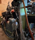
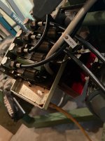
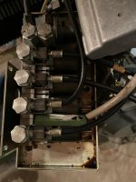
I am trying to prepare for the electro-manual conversion, and the next thing on my list is figuring out how to get the hydraulics to work, mainly for the toolholder release, but hopefully also for clamping the axes for feeds.
This machine was supposedly used in a school (I'm guessing in MI), so I think some of the electrical was modified for US import. I don't have a nameplate photo of the hydraulic system yet, so I don't know the electrical requirements (any guesses for me? what was "normal" in these?). A copy of the hydraulic schematic is attached. It looks like a single phase motor ("M 1~"), but that's all I know right now.
My initial questions are:
1) Have other people gone this route, converting these old "point-to-point" CNC-ish machines to electro-manual use?
2) Can I just hook up electrical power and a (momentary?) switch, to release the toolholder(s)? Is it that easy, or am I barking up the wrong tree?
3) Likewise, will it be somewhat straightforward to hydraulically clamp the axes for feeds? (Once I sort out the servo motor of course... that'll be my next thread.)
4) The specs for this machine suggest it has 3 automatic quill feed speeds (0.02 / 0.06 / 0.12 mm / rev), but I didn't see any indication of what I thought might feed the spindle when I was looking at the machine. Is that what the "O" on the axis selector switch on the panel might do? Nothing on the hydraulic schematic hints to the spindle feed. Or is this just a less equipped model that was sold to a school? Any clues?
5) Is the clear button on the panel, just above the emergency stop, the toolholder release?
I will get the old switch panel, and that is sorta what I'm hoping to use / modify for my electro-manual controls of the hydraulics and feeds.
Any hints / suggestions / direction / ideas are more than welcome.
Thanks,
--Jon


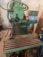
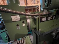
P.S. The "P" version has acme screws, which I think is ideal / fine for a manual machine. From what I have read, the "E" model was more CNCed, and had ball screws. But the whole Maho world is new to me, so I'm kinda drinking from the proverbial fire hose.
I am trying to prepare for the electro-manual conversion, and the next thing on my list is figuring out how to get the hydraulics to work, mainly for the toolholder release, but hopefully also for clamping the axes for feeds.
This machine was supposedly used in a school (I'm guessing in MI), so I think some of the electrical was modified for US import. I don't have a nameplate photo of the hydraulic system yet, so I don't know the electrical requirements (any guesses for me? what was "normal" in these?). A copy of the hydraulic schematic is attached. It looks like a single phase motor ("M 1~"), but that's all I know right now.
My initial questions are:
1) Have other people gone this route, converting these old "point-to-point" CNC-ish machines to electro-manual use?
2) Can I just hook up electrical power and a (momentary?) switch, to release the toolholder(s)? Is it that easy, or am I barking up the wrong tree?
3) Likewise, will it be somewhat straightforward to hydraulically clamp the axes for feeds? (Once I sort out the servo motor of course... that'll be my next thread.)
4) The specs for this machine suggest it has 3 automatic quill feed speeds (0.02 / 0.06 / 0.12 mm / rev), but I didn't see any indication of what I thought might feed the spindle when I was looking at the machine. Is that what the "O" on the axis selector switch on the panel might do? Nothing on the hydraulic schematic hints to the spindle feed. Or is this just a less equipped model that was sold to a school? Any clues?
5) Is the clear button on the panel, just above the emergency stop, the toolholder release?
I will get the old switch panel, and that is sorta what I'm hoping to use / modify for my electro-manual controls of the hydraulics and feeds.
Any hints / suggestions / direction / ideas are more than welcome.
Thanks,
--Jon


P.S. The "P" version has acme screws, which I think is ideal / fine for a manual machine. From what I have read, the "E" model was more CNCed, and had ball screws. But the whole Maho world is new to me, so I'm kinda drinking from the proverbial fire hose.


