What's new
What's new

Making a slotting/shaper head cutter

ballen

Diamond
Joined
Sep 25, 2011
Location
Garbsen, Germany
I need to cut a 5/32" = 3.97mm key slot in a steel gear. I have a Deckel slotting head chisel, marked 4mm, which I had planned to use. But to my surprise it is 4.5mm wide, and also too wide in the other dimension. So I decided to make my own.

The chisel body is made from some steel stock, 20 x 20mm, which I milled down to 16 x 15.5mm. I turned down a portion of it to 12mm (probably should have picked 11mm, so it would fit nicely between the table slots).

To make the through-slot, I clamped the body at about 12 degrees in a vise (angle measured from some stock Deckel HSS chisels) and drilled 1.5mm holes in the 4 corners of a 4 x 16mm rectangle. Then I drilled out most of the material with a 3.7mm bit, and finished the slot with a 4mm end mill. Retainer is a 5mm grub screw.

attachment.php


attachment.php


The cutter itself comes from a strip of 4mm x 16mm HSS, sliced off with a abrasive wheel and then roughly ground to shape on a hand grinder. I've done a bit of relief on the outside, and plan to also grind a bit of relief on the sides. Hints welcome, I have not made a slotting cutter before.

attachment.php


attachment.php


Cheers,
Bruce
 
I like the idea of using a blade instead of the usual square bit (wich I did) but doesn't the fact that the tool is held at an angle affect its ability to stay put ?
 
Hi Tien,

Doesn't the fact that the tool is held at an angle affect its ability to stay put?

You have a lot more experience than me, so now you've got me worried. :scratchchin:

I hope this isn't a problem, I'm going to try the cutter later today on some scrap to see how it works. If it shows any tendency to walk out of the holder, I guess I have two options. Either I'll cut off the end and make a 90 degree slot instead. Or I can put a little "dimple" or "divot" on the bottom of the HSS piece, which engages the grub screw. That should hold it in place.

Do you know if a solid carbide bit can make a clean starting dimple in HSS? Or will I just destroy the bit?

Cheers,
Bruce
 
The most common method is to use as stiff as possible holder in mild steel (largest diameter) to resist tool deflection. Then braze or silver solder a ground HSS bit to that. I think your tool will both deflect and slip.
 
On another note, you should consider using an under size cutter, say 1/8" and then sneak up on the key width. This is also a very common method, as it greatly reduces tool force and deflection.
 
I finished the cutter today. Hollow ground the front face using a wet grinder that I normally use for woodworking chisels and planes, ground some relief on the sides.

First test was on a block of aluminum:
attachment.php


Second test on steel:
attachment.php


In neither case did the cutter show any signs of working free, nor did the holder show signs of taper or deflection: the shavings just peeled off.

After those two tests I cut the keyway in the gear:
attachment.php


Two random unrelated questions:
(1) For me the most time-consuming part of changing FP2 heads is removing the rear stop/retainer from the back of the long reach head. This is held on with two vertical M8 SHCS which are a pain in the *ss to get off. Does anyone have a trick for that?

(2) I noticed that there is a puddle of oil gathering behind the horizontal spindle, see photo below. Would it be OK to drill a small drain hole to let this return into the mill, blocked with a piece of felt to keep out chips and dirt? Or is there some seal that I can replace to prevent this puddle?

attachment.php


Cheers,
Bruce
 
Two random unrelated questions:
(1) For me the most time-consuming part of changing FP2 heads is removing the rear stop/retainer from the back of the long reach head. This is held on with two vertical M8 SHCS which are a pain in the *ss to get off. Does anyone have a trick for that?
Agreed. They are a massive pain. I have still not worked out what tool works best for these. A typical hex key is cramp inducing.. Looking for some inspiration!

(2) I noticed that there is a puddle of oil gathering behind the horizontal spindle, see photo below. Would it be OK to drill a small drain hole to let this return into the mill, blocked with a piece of felt to keep out chips and dirt? Or is there some seal that I can replace to prevent this puddle?
Nice to see that my machine is not the only one nursing a pool of oil there. I'm hoping Ross or someone tunes in and gives some hints on how to fix it.
 
Hi Bill,

Agreed. They are a massive pain. I have still not worked out what tool works best for these. A typical hex key is cramp inducing.. Looking for some inspiration!

The only way I have found to remove this is to hold a short stub of 8mm hex key in place with one hand, then turn it bit by bit with an 8mm wrench. And each time I slip, the hex key stub and wrench fall into the pictured oil pool!

Nice to see that my machine is not the only one nursing a pool of oil there. I'm hoping Ross or someone tunes in and gives some hints on how to fix it.

Unless I am told otherwise by Ross or Peter, the next time I have the ram off, I'll drill a 6mm hole through it, centered under the horizontal spindle, and as far forward as possible. Then I'll stick a pencil-eraser sized plug of felt in it, to filter out chips and grit. That won't solve the problem but will remove the symptoms.

One further related question, is there a good way to locate a slot precisely when using the slotting head? The only way I could see was to attach a fiducial reference point to the table (321 block, clamped), make a test slot, measure offset of test slot from fiducial, then setup the work, measure offset to fiducial point, shift table, and cut. What's needed is some type of indicator that can be shifted into place, then pulled out of the way, then swung back in exactly the same place. I see another tool being added to my collection, but don't know which one...

Cheers,
Bruce
 
One further related question, is there a good way to locate a slot precisely when using the slotting head? The only way I could see was to attach a fiducial reference point to the table (321 block, clamped), make a test slot, measure offset of test slot from fiducial, then setup the work, measure offset to fiducial point, shift table, and cut. What's needed is some type of indicator that can be shifted into place, then pulled out of the way, then swung back in exactly the same place. I see another tool being added to my collection, but don't know which one...

You mean in a bore ?

If so, that question as already been adressed :

Ross's method for a part held centered in a dividing head or rotary table :

"This method is i believe the most accurate but requires more time and effort...
First off check that your tool is set square to and axis, lets say the "Y".....Tool steel blanks in a round bar must be checked....use the indicator along each side of the tool bit and correct as required, checking that
the cutting face is also true....(i usually grind my shaping tools without any side clearance...Flat on the sides so the entire edge works on the slot side)

Once the tool is set square then you have to center it on the work.....Mount the part on the rotary table or dividing head......set the work to run true with the rotary.
Mount a dial indicator to the rotary and position it to read on one one side of the tool bit at the cutting edge.
Rotate the rotary to find the lowest dial reading.....while moving the "Y" back and fourth .Set the machine dials (X) or DRO (better) to zero

Move the "Y" slide out to give the indicator clearance and rotate the work with indicator 180*...Now move the indicator (Y) back and read the tool side (opposite) same as previous...
Note the reading (X) of the new position...move the slide to a value half the total and the tool will be centered to the table rotation....
"

Now a little more crude :

You can either put a pin in the bore, come and touch the side of the pin with the side of the tool and then move the table of half the diameter of the hole + half the width of the cutting edge, or you can plunge the tool in the entry of the bore and move the table so that both corners of the cutting edge leave the same marks in the hole (of course, make sure your tool is square to the work laterally).

http://www.practicalmachinist.com/vb/deckel-maho-aciera-abene-mills/shaping-head-304963/#post2564602
 
Hi Tien,

Thanks for repeating that earlier advice. In the end on the previous project I ended up turning and modifying a 17mm hex socket, so was able to avoid slotting. I guess that means I had not internalized Ross's advice.

This time around, I put a 5/8" pin in the bore, touched off on both sides of the tool, and split the difference. The result was fine, but I want more precise methods for the future.

Tien, I should have listed you along with Ross and Peter as one of the most trustworthy sources of advice here. Any suggestions regarding the "oil pool" or the hard-to-remove bolts at the rear of the FP2 long-reach vertical milling head?

Cheers,
Bruce
 
Bruce

Thank you for the kind words but the best advice I can give you is to NOT take everything I say for granted ;)
I'm only a hobbyist !

As for your machine, I never had an FP2 so I don't really see the problem you are mentionning with the long reach head.
Wouldn't it be possible to design clamps where the bolt would be mounted sideways ?
Do you have to remove the bolts completely to get the head off the machine ?

As for your oil leak, I can't see no reason why your plan of drilling a hole wouldn't work, assuming it really returns the oil in the gearbox whatever the position of the ram will be (and not on the belts !)...

But may be I can suggest something else.


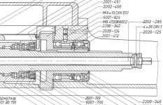
I can't figure out a way to get a good sealing of the rear bearing arrangement on the FP2, due to the spindle and its slots.
Those slots will always make a nice passage for oil trying to find its way outside.

Deckel FP2 rear bearings.jpg

The thing I think about would be to replace the end cap 2200-346 with a modified cap that would enclose the spindle all the way rear (almost), a bit lithe this :

Deckel FP2 rear bearings modified cap.jpg


I can't see why it wouldn't solve your problem without having to drill any hole in the casting nor altering the machine function in any way.

Plus what I don't like in the idea of an external drain hole, is the risk for the oil to get contamined with dust (my shop is pretty dusty whatever I do).
Of course you mentionned a felt plug but chances are that if it acts good as a filter, it will quickly get clogged.
There seems to be a fair amount of oil in your "pool", suggesting that you'd need a drain hole that wouldn't be too restricted.
It's probably better to get the oil back to where it belongs before it gets out.

I realise that the end of the drawbar shows a larger diameter than the rear part of the spindle on your machine. Slightly different from the drawing I have but that could probably be easily modifed

With thick walls enough for the cap, you could probably make good use of your slotting head to cut an internal sloped slot at the bottlom to ease the return of the oil.
Just a thought. May be I'm overthinking the problem.

Deckel FP2 rear bearings modified cap with tapered slot.jpg

As for your tool reference problem, what kind of precision do you need ?
Whenever your work is held in the dividing head, you can use a centering scope in the spindle prior to mounting the part, to locate the tool very precisely (precisely assuming your chuck or setup will place the part true to the spindle axis, that is)...
 
Last edited:
Hi Bruce,

Thanks for the thread on the slotting head and cutter. I need to make a new drive ring for my monarch lathe and a similar task is in front of me.

For removing the long reach head I have a ratcheting combination wrench with a short length of hex key held in place by snap rings. The hex key extends just enough out of the wrench head to fully engage the screw. If I get a chance tonight I will take a picture of it. You can cut enough of a grove in the hex key stock with a carbide lathe bit but the bit doesn't like it.

I like TNB's suggestions about managing the oil collection in the trough. I started to make a tapered cone to fit back there out of some delrin I had lying around. Maybe with some time home over the holidays I'll get a chance to finish it off and will post.

Thanks again for the timely thread.

John
 
Hi John,

For removing the long reach head I have a ratcheting combination wrench with a short length of hex key held in place by snap rings. The hex key extends just enough out of the wrench head to fully engage the screw. If I get a chance tonight I will take a picture of it.

Please post a photo! For those who want to know what it looks like, here's the spot. This is an 8mm wrench, so there's not a lot of room there.

attachment.php


I like TNB's suggestions about managing the oil collection in the trough. I started to make a tapered cone to fit back there out of some delrin I had lying around.

If you make one and it works, please post a photo. I'll have to look more closely at the rear part of my horizontal spindle, not sure if this could be made to seal well enough. But the basic idea is good, make use of gravity.

Cheers,
Bruce
 
Hi Tien,

As for your machine, I never had an FP2 so I don't really see the problem you are mentionning with the long reach head.

I just posted a photo of the area. Sounds like John has a solution. I need a really small 8mm ratcheting wrench.

I like your idea about making an oil catcher. Need to look to see if the ID of that can make a proper seal. Also worried that oil is going to work its way out from beneath the ring that's visible in the photo.

In the worst case, if I have to go with the felt, I think it will work even if there is a tendency to clog. The oil accumulation you see is from more than a year. So provided that the felt passes a few drops per hour, the oil will drain back where it belongs.

Regarding the centering question, it's no problem for me to reference things precisely to the SPINDLE. The question is, how to reference them precisely to a slotting chisel? Ross's solution is to use a rotary table, and by rotating this 180 degrees you can locate it's center relative to the chisel position. Then center part on rotary table.

Cheers,
Bruce
 
Wondering about teh bolts on the long reach head...

Why not use a standard bolt with a hex head...turn up a spacer sleeve that replicates the Allen head ...shorten the bolt till just the hex head is just proud of the casting spaced out via the
sleeve....That way no additional tooling would be required, jsut an end wrench on the hex....If need be shorten the hex for clearance.....

Cheers Ross
 
Hi Ross,

Why not use a standard bolt with a hex head...turn up a spacer sleeve that replicates the Allen head ...

If there is room, that's a good idea. But I don't want to have to remove/replace the wrench 50 times x 2 bolts, and there is not enough room to fit a regular socket + ratchet, and perhaps not even enough room to swing a ratcheting wrench once the bolt starts coming out. Curious to see John's picture. Seems like a fine solution, since it works!

Cheers,
Bruce
 
Hi Bruce,

Here is photo of wrench in use:

IMG_0672-M.jpg


Here is a more detailed shot of the length of hex key stock held in by the snap rings:
IMG_0671-M.jpg


This one uses a craftsman wrench whose ratcheting direction is determined by which side you use. I have since made a second one (out on loan) using a mac tools wrench which has a selector lever. They work equally well.

I would love to claim this as my idea as it works so well however the wrench came from Chris999.

John
 
I like your idea about making an oil catcher. Need to look to see if the ID of that can make a proper seal. Also worried that oil is going to work its way out from beneath the ring that's visible in the photo.

In the worst case, if I have to go with the felt, I think it will work even if there is a tendency to clog. The oil accumulation you see is from more than a year. So provided that the felt passes a few drops per hour, the oil will drain back where it belongs.

Regarding the centering question, it's no problem for me to reference things precisely to the SPINDLE. The question is, how to reference them precisely to a slotting chisel? Ross's solution is to use a rotary table, and by rotating this 180 degrees you can locate it's center relative to the chisel position. Then center part on rotary table.

Wich ring are you talking about ?
Another thing you might consider is that a good deal of the oil leaks on a Deckel come from the main body / ram junction.
The sealing between those two members is far from beeing perfect even with new seals. One always see drops of oil finding their way out running on the underside of the ram.
Chances are a drain will just add to that phenomenon because the flow won't be strong enough for the drops to fall and they will just stick to the underside of the ram.


As for the centering of the slotting cutter, I was thinking about the spindle of the dividing head. It is true that I could have been clearer.

Mount the scope in the dividing head spindle (this is where having an swivelling eyepiece comes in handy), locate the cutter mounted in the slotting head and zero the machine, mount the part to be worked on in place of the scope.
I also used this tip for centering gear cutters, since I couldn't figure out a way to do it more precisely.
 
Hi John,

Wow, nice paint on your mill!! Makes mine look old and ugly.

I don't own any ratcheting ring wrenches, will buy an 8mm one for this. Would it help to get one with a knuckle?

I just realised the SHCS are M10, the hex keys are 8mm. I wonder if it would be better to epoxy or soft-solder two short bits of hex key stock into the SHCS. (I don't want to hard solder them because that might soften the screw.) This is like Ross' idea of giving them hex heads, just that the hex heads on M10 bolts would be 16mm (ISO) or 17mm (DIN) wide and there would not be enough space for a wrench to go over them.

Hi Tien,

OK, I got it on the spindle, thanks. This won't work so well for me because my dividing head has an MT4 taper, my microscope an SK40.

Also, in thinking some more about the plastic oil-collecting sleeve, I saw one possible issue. When the horizontal quill is fully extended, the drawbar "nut" visible in my photo will be pulled right up to the ram body. So the oil collector would need a large enough ID for that to pass through; it can't be a tight fit.

Regarding oil leaks between the bottom of the ram and the top of the Y ways, fortunately that's not an issue on my machine. In fact that entire area is soaked in oil flung about by the long horizontal driving gear. That does not leak out, probably because there are oil catchers on both sides of the long gear and in the back rear below the Y lead screw.

Cheers,
Bruce
 
Also, in thinking some more about the plastic oil-collecting sleeve, I saw one possible issue. When the horizontal quill is fully extended, the drawbar "nut" visible in my photo will be pulled right up to the ram body. So the oil collector would need a large enough ID for that to pass through; it can't be a tight fit.

No need for it to be a tight fit with the spindle, wich would be useless due to the slot anyway.

The idea is just to have a tube with a recessed end to collect the oil that may pass between the current cap and the spindle and prevent it from getting outside.
One can expect that any oil that would run along the spindle woud be centrifugated before it gets to the end, and then get back to its starting point.

As for your drawbar nut, all you have to do is to reduce its diameter or make a smaller one if you don't want to modify this one.


Back
Top