What's new
What's new

Potential FP2 shipping damage

Nice Guy

Aluminum
Joined
Mar 14, 2020
Location
Mom's basement
I recently purchased a 1982 FP2 in excellent condition. I don't think it was a deal but a fair price.
I had to move it from Portland to Alaska Marine lines in Seattle. So I hired a machinery moving company that quoted 4K for that move. I think that's expensive but I wanted it crated and shipped without damage. I emailed the rigging instructions from the manual and confirmed that they were going to block the knee like it said and take off the 400+lb rotary table before shipment. I pointed out that the maximum table load was 800 lbs and that bouncing the machine around with a 400lb load would exceed that if it sees 2G's.
What happened was that they showed up with a flat bed and loaded the mill on the flat bed, without removing the rotary table or blocking the knee. They secured it to the flatbed by strapping over the back end of the table so that any loads the strap saw would be transmitted to the Z axis moving mechanism. Then they drove it through Portland to their warehouse to crate.

What is the chance that the accuracy of the Z axis mechanism would be affected by ignoring the rigging instructions and instead transporting with increased load on the table?

If I check DRO movement vs that on the dial when I change height would that pick up the damage?
If I support the table so it isn't preloaded by gravity would it show up as increased Z axis backlash?

deckel strapping.jpg
 

Attachments

  • image0(1).jpg
    image0(1).jpg
    20.3 KB · Views: 241
The machine pictured is a conventional manual machine, That is having more or less conventional mechanical screws (Acme) with bronze nuts.
Don't think their moving setup will have caused any appreciable damage to your machine.
The precaution of removing the table ASFAIK is for the CNC machines that are fitted with ball screws. There, the issue is the "hammering" effect that can happen between the balls and the screw and nut.
It can brirnell the contact surfaces and cause rough operation or eventual failure of the screws....
Your Acme screws have full surface thread contact with the nuts (not points like the ball screws)
Think you will be fine.......

How about some better photos of your new machine when all gets settled.
Cheers Ross
 
I agree with Ross. Also, even if the DRO disagreed with the Z micrometer dial, how would you know whether that was wear or damage unless you mapped the wear ahead of time? And, even if there was damage, I'd expect it to have occurred to the nut and not the screw. The DRO test can tell whether the screw pitch varies along the length, but won't say anything about the nut.

I suggest you check the load path for the screw and nut for loose screws, cracks, and similar signs of overload.
 
Ross I'll post pics of the machine once it arrives. This specific machine has been discussed on the forum before. It's the one that Milacron acquired in 2016. There are some pics in this thread:

https://www.practicalmachinist.com/...xis-328865/?highlight=deckel,+fp2,+Heidenhain

It's the machine that has the last serial number for FP2s listed in this thread:

Interesting serial number information for the FP2 series
FP2 SN.jpg

I bought it from the person that Milacron sold it to, who is, oddly enough, another radiologist. We all secretly want to do something other than stick tubes in people's butts for a living.

The rigging instructions I was using were from an FP2 manual for that vintage FP2, the manual for the FP2NC says that on the cover I believe.
rigging instructions.jpg
Rigging figure 1.jpg
Since the purpose of blocking the knee is to unload the z axis mechanism I assumed that removing an additional 400lbs would be the appropriate, even more so when it was transported without blocking.

If damage occurred to the screw I think it would be where it was loaded at the level of the nut. Assuming that the table did not change its height during moving, it would be different from wear since it would be focal and wear would occur over a distance of travel.

I don't think that damage to the nut would change the DRO reading. I thought that plastic deformation without fracture might show up as backlash. I don't think I could discriminate that from wear beyond being much different from the other axes, 0.003” X axis and 0.008” Y axis. I will check for the obvious physical damage you describe.
From the seller:
s-l1600b.jpg
 
Additional thoughts:
Via photo, the "Z" axis appears to be at or almost at full down....so less chance to have any problem with bending the screw...
the 400# load limit on the table for work weight is ,it should be remembered a dynamic load...and at that things like feed and in fact rapid moves are accounted for.
Your setup was static and will tolerate quite a bit more load without any issues. Also strap placed close to the ways means that little bending load has been applied to the slide ant its ways.....

Further, wear on the screw and ways almost certainly will be greatest at about 1/3 down on the "Z" axis as this is where most work happens. The nut wear will be constant....
For my money think you will be hard pressed to detect any difference as to screw wear . On the horizontal slides wear can be detected via changing backlash....On the vertical
the weight keeps the lash out so it won't be as easily detected.....think the best way to properly evaluate any nut wear is to remove the vertical slide , the nut and gauge it relative to a good thread or unworn portion of your screw.....Not a terrible job, some posting on this forum with photos if you search.
Suppose you could block up the "Z" slide and note the free rotation for the screw in both directions to take up on the nut.(degrees of rotation vrs. pitch= backlash)..but that method does not account for any lost motion (linear) in the thrust bearing for the screw.

Personally, if the slide moves smoothly throughout its range ,does not make any "bad noises" and has somewhat the same effort throughout its full movement then i would call everything good and move forward to putting the
machine in service. If there has been any deformation of the nut think it would greatly affect the freedom or ease of movement of the screw....

Cheers Ross
 
The bronze nut and "regular" screw on that machine is much less likely to suffer dammage from brinelling than a ball screw....but the thrust bearing at the top of the screw could.

I had to replace that bearing on my machine for that very reason, and it's no fun task. I was trying to figure out why the z-movement felt a bit heavy for my likings, and discovered that the thrust bearing (it's a roller bearing iirc) was very slightly brinneled.
Barely detectable to the naked eye but visible anyway, and definitely something that required an extra effort at the handwheel. Note that the brinnelling was not something obvious from the handwheel rotation, and I really had to focus on it to figure out the problem.

You have to take the "knee" off the machine and to tear the main shaft down (wich includes playing with some tapered pins)...
Then you can call yourself lucky if you've not disturbed the bevel gears when everything is back together.

So my advice would be to crank the z handwheel up, paying extreme attention to the slightest "dents" you could feel in the handwheel motion.
 
Anybody know a Deckel service engineer?

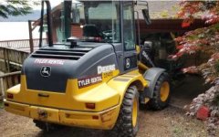
So the mill was delivered yesterday. I used a rented John Deere front end loader to pull it off the truck and put it in the garage. Without a mast it worked better than a forklift and I was able to place it completely on the slab.
smLoader.jpg
The rotary table is off and the Z-axis seems like it's harder to move than it should. When I turn the hand wheel it feels like there is a "texture" to it that isn't on the other axes. Does anyone know of a service engineer with experience with this type of machine that I could pay to make a house call? I want to get it fixed regardless of whether the mover will cover the expense.

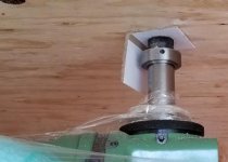
The movers paid someone else to make the crate for the machine. The crate was too small and the top of the spindle/drawbar rode against the top of the crate:
SmTop.jpg
Either they didn't know enough to rotate the head like it is the rigging diagram or they didn't care. They put a little piece of cardboard between the two that was almost worn through:
SmCardboard.jpg
Any sag in the palette when it's picked up would be transmitted to the spindle/drawbar via the crate. Another thing for the service engineer to check.

Part of the sales pitch and quote was that it would be shipped in a barrier bag with a dessicant. It spent a couple of weeks next to and on the ocean so I thought that it would be nice to protect from the salt in the air. It came with a few loops of packaging wrap, no barrier bag. There is some cosmetic damage as well that looks fresh. I'll verify with the seller that it's new.

Until the shipper got a hold of the mill I was excited about getting it. Now it's turned into a big hassle. I sent them an email with pictures and let them know that I would have to get an atty involved to know how to handle it.
 
Congrats on your new machine! Please post some photos.

These machines are remarkably robust, so I think it's unlikely that Z or the head is damaged.

I suggest that you loosen the Z gib, and lubricate the support with the correct oil. Also check that the sump where the Z-axis leadscrew goes is properly filled. Then tighten the Z gib until it just grabs, and loosen half a turn. Run it up and down with power feed a dozen times. Then re-asses.

Keep in mind that there is a difference between Z and the other two axes. X and Y have no load, whereas Z is always under a couple of hundred kg of load. So they don't feel the same.
 
Does anyone know of a service engineer with experience with this type of machine that I could pay to make a house call? I want to get it fixed regardless of whether the mover will cover the expense.

I really don't know if it would help you.
Unless the z-axis feels really heavy and the handwheel is close to seized, it's all about the "feel" when you crank it.

Not something a phone call will tell you (or the service engineer at the other end of the line) much about.

Keep in mind that there are at least one set of bevel gears and then yet another gear set between the handwheel and the screw on that machine. Add the thrust bearing and a few other bearings, plus the fact that the screw and nut are permanently loaded with at least 3/400kg worth of good german iron, and you'll realize that the "feel" can not be totally direct.

On the other hand, it would be interesting to know how much weight is required at the z-handwheel of a good condition / properly lubed machine with the regular table to get the axis moving.

Bruce's advices are good ones btw !
 
Sometimes I find it better to pay someone to teach me a skill rather than paying them to do a task. With the OP’s location in Alaska my guess is (when covid travel concerns decrease) a few days of one on one brain picking with someone like alfaGTA would be very worthwhile.

L7
 
With the OP’s location in Alaska my guess is (when covid travel concerns decrease) a few days of one on one brain picking with someone like alfaGTA would be very worthwhile.

That said,I'd looooove to visit Alaska ! :D
 
The biggest problem I see is that the shipping issues have spoilt your expectations and potential enjoyment of the machine.

My advice would be to get it set up as quickly as possible and start making chips. That would reveal the actual condition of the machine, and I'm sure it's going to be just fine.
 
I understand that the Z axis will feel different since it is preloaded by gravity and the others aren't. The rotary table is off now so its just the weight of what won't come off.

Since the main expense would be for time and travel it might be more cost effective just to buy any parts that could have been damaged and swap out the old ones. If the old part is still good I can keep it for a spare.

I'm reluctant to take it apart myself but certainly interested in the mechanicals if it gets taken apart by someone who knows what they are doing. If the doc who owned it before me told me he partially took it apart to try to fix something I probably wouldn't have bought it. Not that we are all dopes but having it taken apart by someone who's never seen the inside of any milling machine may be asking for trouble. Nobody wants their surgery done by someone who has never seen the inside of any mammal. I could see flying to some place to see how its done if someone was going to take theirs apart.

I will look and see if I can follow Ballen's guidance. I'm waiting for a rotary phase converter to arrive so I will be able to power it up after that. I ordered it 10 days ago but Fedex says it will take 3 weeks to get here, the joys of AK life.

TNB by "house call" I meant flying to the site of the mill, not just a phone call. I just looked and a round trip flight from Paris to Ketchikan, AK is only 100K airline miles. I think I am sitting on 300K miles right now. I used to use them for friends and family who wanted to visit but most have checked AK off their bucket list now so they get used at a slower rate than they accumulate.

A pic from the seller:
IMG_3501(1).jpg
 
The biggest problem I see is that the shipping issues have spoilt your expectations and potential enjoyment of the machine.

My advice would be to get it set up as quickly as possible and start making chips. That would reveal the actual condition of the machine, and I'm sure it's going to be just fine.

There is a lot of truth to this.
I got very angry when I saw that they had disregarded the rigging instructions after I emailed them a copy from the manual, confirmed that they understood them and would follow the instructions prior to hiring them.
As long as there isn't something obviously wrong I will try to use it once I power it up. I just feel I have a responsibility to get it fixed if it has been damaged.

All the damage I can see so far Peter is cosmetic. Chipped paint. Bent drip pan.
 
I totally understand your desire/need to know that everything is as it should be, and in tip top shape...that machine deserves that. I was a buyer for it before "Milicron" repaired and sold it to the owner before you.
Maybe you could arrange a "Skipe" connection and do an inspection/overhaul with some remote assistance.....In a way its like exploratory surgery.
Some basic idea of what you need to accomplish and you just follow the parts into the interior.....Take notes and photos (i like notes best) ...If in doubt about how to proceed , you just need to ask...
Pretty much this place never closes.....
Don't need tons of special tools to work on these machines. For getting to the thrust bearing of the vertical however you will need a method of lifting the vertical casting off the vertical box ways.
Chain fall on a heavy rafter or a shop crane (engine lift) will work.


Sorry to hear about your rotary converter....Looking at the machine and your seeming interest in things "correct"
Would have wagered that you would have gone for the Phase Perfect power solution....much nicer than rotary and quiet as well, not to mention that
it would provide power to all three phase devices in your shop, which will without doubt increase in population...Nobody stops with just a single machine....

Cheers Ross
 
Ross that's a wager you would have won. I was planning on getting a phase perfect system and probably still will. When this shipping problem started I decided to just get something that would run it asap. I bought one of the plug and play units from American Rotary that was in stock thinking I would get it without too much delay.

One of the reasons this situation set me off is that I feel that I am responsible for the machine and that it reflects poorly on me that this happened. I picked what was supposed to be a professional rigging company, looked to see if there were complaints on line, sent them the rigging instructions and made sure they understood and agreed to follow them. Short of flying there to supervise I don't know what else I could have done. Before I hired them I thought about designing and having a professional shipping container built for the machine. I did that for test equipment I built for a NASA subcontractor 40 years ago. But I thought maybe I was getting a little OCD with that idea so I went with the riggers. After this experience I will build one myself for moving the machine.

I was going to try to buy an engine lift today to lift the rotary table up on to the machine. Try is the operative word there. Inventory is usually thin to nonexistent here. A couple of weeks ago I rushed across town to buy what I was told was the last palette jack for sale on the island only to find out it only existed in cyberspace.

I appreciate the encouragement on working on it myself. That may be the only option for a while with this COVID business going on.
 
So its absolutely required that you have a copy of the parts manual for your machine!
Must be the correct year so the mechanicals are the same...There are lots of little differences as the machines evolved.
I can't help you with this as i don't have a list that is of the correct vintage. Would bet however that someone on this board has a copy and could provide a copy should you not
already have one....
Parts book gives the layout of the various sections of the machine and is invaluable to any serious mechanical repair work.

Cheers Ross
 
I was able to download a copy of that.
It says it's for the 2202 version of the machine and the diagrams match the configuration of the later machines.
It may have been from this site: https://onedrive.live.com/?cid=547F...D561F!6728&parId=547FE296ECFD561F!209&o=OneUp

The only bearing I can see that would be near the top of the Z axis screw doesn't look like it has the configuration I would expect for a thrust bearing, circled in blue.
z screw.jpg
 
The thrust bearing i believe is below the one you circled...# 25130004/81104 INA
That is a flat plate ball or roller thrust bearing (didn't look up the number so don't know which...
That number is a generic number, that bearing should be available from any good bearing house.

https://www.motionindustries.com/products/sku/00134295

There are two other bearings there. Above the thrust is a needle roller bearing (G20x 26x 4 INA) to locate the screw radially...then above that is the bearing
you circled. (16004 DIN 625)..that is a deep groove ball bearing. It carries the thrust and radial location for the drive gear....

Those bearings again are generic and available through commercial outlets...Google the DIN spec and it will tell you the class of bearing Deckel specified.
Could easily have all three bearings on hand before removing the vertical slide....

Disassembly appear pretty straight froward.....Remove the nut on the end of the screw, un-bolt the fanged carrier at the bottom and pull the assembly with shaft out, leaving the gear behind.
The only rub here is that to get to that gear and nut you have to remove the vertical slide and open the access plate that covers the works.
Cheers Ross


Back
Top