sneebot
Stainless
- Joined
- May 14, 2001
- Location
- Massachusetts
I am going through the Deckel FP3 Activ Electrical Schematic and I'm not quite sure how to interpret their notations.
I'm working on getting the DC drive hooked up in the FP3 machine I purchased some while back. Previous owner had swapped the original drive with an underpowered replacement and monkeyed with some of the wiring in the process. I found an original drive and have installed it. I believe I have made all the connections to the drive correctly but the wiring around the A2B PCB has been modified and I am trying to figure that out.
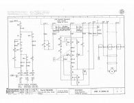
The Deckel schematics have 'X' numbers all over the place (as in attached sheet)- X1.8, X8.9 ect ect ect. I believe these are pointers to other locations but I'm not sure how they work exactly.
There are also singular numbers, usually on either side of switches, relays ect.-- are these supposed to refer to wire numbers?


