Hi Cliff,
Sorry for the slow reply.
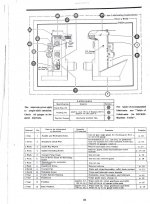
#7 in the schedule below: While there are detail pages for many of the items in the schedule, there is none for this. The only logical place I can see to lubricate the hand wheels is between graduated dials. Is this correct?
These are "safety wheels" which can spin freely. They may have an oil nipple on the side or center which puts oil into the spinning bearing in the center of the hub.
2) #11 in the schedule below: This table indicates that the only lubrication here is to disassemble and lubricate the spindle bearings with Isoflex grease every one year, or 8000 hours. Another schedule (also pictured below) suggests this, in addition to oiling it in the ground keyway monthly. I'm not sure if this is an updated set of directions or if it applies to a different model of spindle. I'd hate to wash out the Isoflex grease with oil.
In the first case #11 is the horizontal spindle. Should have the grease replaced from time to time. Ross (AlfaGTA) has posted very clear step-by-step instructions for this. Was also recently done by Thanos here, again with pictures and a description.
In the second case (vertical head) the vertical spindle is "sealed" and as for the horizontal spindle, should have grease replaced from time to time. But the oil you feed in at the top goes over the bevel gears and bearings external to the spindle. So just follow the instructions.
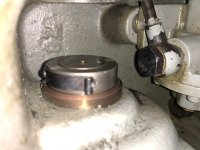
Unfortunately, there is absolutely no doubt that someone, at some point, pumped the saddle full of grease (photo below). I will start looking into just how major a surgery this will be.
Sigh. You need to remove the horizontal table and support, and clean them out.
The good news is that there are detailed step-by-step instructions on this. Given that your machine is in good shape, it will probably take you some tens of hours to do this. Depending upon where you are in California, there may be someone local who has already gone through this.
Thank you very much for your help and advice, Bruce. I hope I'm not wearing out my welcome and making you sorry you offered your assistance.
Not at all. I have a large debt to others on the board here (Ross, TNB, Peter,...) who helped me to get my machine sorted. So I'm paying that back. Here are links to two threads that you should read through:
Getting the grease out of my FP2
Bill's FP1 grease removal thread
You have some work ahead of you, but the good news is that there are people here who have gone through every step. So you are not "flying blind".
Cheers,
Bruce