chibbe
Plastic
- Joined
- Nov 30, 2007
- Location
- Stockholm / Edsbro
Hi all,
So my deckel is just brought back from the dead.
(It had problems electronic problems in some cards) I have never used this machine before so I dont know how/when this problem started.
The problem is when I push the spindle start button (Left or right with or without spindle brake on doesnt matter) I hear the spindle brake goes on and off like every second. I removed cover for gearchange solenoid/motors I see that all three motors trying to put gears in so all this seems fine!?
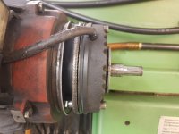
I removed the backcover of the spindle motor and can see the spindle brake moves but the motor is not Rocking/moving at all!
In the big electrical cabinett I see that Relay K10 and K1 is pulling/releasing after each other every second or so and K3 is pulled constanly.
If I use a stick to force the motor slightly in any direction during the machines attemt to put the gears in. I can eventually get the spindle to start and this works at all different speeds and in both directions. Ones the spindle starts at a selected speed, it starts directly the next time I hit the start button again.
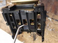
I thought relay K3 was the problem with poor contact. My voltage meter wasn`t fast enough to measure the voltage passing over K3. But Resistance check showed some varius ohms up to about 120ohm so I took it apart.

All contact surfaces looked good but I cleaned them anyway and put it back together, measured resistance and it was more or less nothing. Back in the machine again but still same result.
I also measured the 3 big resistors, they all was 56 ohms.
Thanks to Ross "AlfaGTA" explanation in this thread below I got a understanding how this system should work:
https://www.practicalmachinist.com/...ene-mills/deckel-fp-nc-spindle-speeds-295614/
I also copy/paste Ross writing here below:
The wiring diagram you post is for the first generation FP-NC's.
Your evaluation is correct. The main drive motor is a two speed 3 phase induction motor....
What gives all the spindle speeds is a conventional (more or less) gear box, with sliding gears to change the ratios.
Shifting is accomplished by using the main motor to "rock" the spindle while the gears are moved by small DC motors moving the three shift forks.
Position of the forks and thus the gears is controlled by micro switches being actuated by cams to tell the control when the selected gear is engaged.
The rock of the spindle is accomplished by dropping the motor voltage using large resistors (r1,2 & 3 in your print) , switched on (K3) for shifting.
Sequence goes like this ...Once the speed is selected (note only specific speeds can be programmed..not variable due to the gear transmission) the
motors to move the shift forks are energized, at teh same time the motor brake is released and the main drive motor is turned on (low voltage via resistors) for an instant.
The sequence repeats for 3 cycles about once every second. Then the motor (main) is reversed and the cycles are repeated, all teh while the shift motors are powered and trying to move to the programmed
rotational position.....
There is another reversal of the main motor and a final three short power pulses to the main motor.....If the gears don't engage at this point the machine faults....
The motor/brake/reversal cycles will stop as soon as the shift switches indicate that the selected speed has been reached...
On my FP4NC this usually takes takes about 2-4 motor/brake engagements...(3-5 seconds)
Its a complex system but it works pretty well if the main motor relay contacts are in good shape. Owing to the low voltage used on shifting, any burned or pitted contacts will affect teh motors ability to rotate and thus
make shifting slow and unreliable....
Cheers Ross
Here is a picture from my orange book of the motor schematic:

If the system is designed to rock/move the spindle in both directions during gear change? Doesnt relay K2 need to be pulled next after the K1 has been pulled and released? But still, my spindle isn`t rocking/moving at all even if just K1 and K3 is on.
Any thoughts/experience?
Best regards
Henrik
So my deckel is just brought back from the dead.
(It had problems electronic problems in some cards) I have never used this machine before so I dont know how/when this problem started.
The problem is when I push the spindle start button (Left or right with or without spindle brake on doesnt matter) I hear the spindle brake goes on and off like every second. I removed cover for gearchange solenoid/motors I see that all three motors trying to put gears in so all this seems fine!?
I removed the backcover of the spindle motor and can see the spindle brake moves but the motor is not Rocking/moving at all!
In the big electrical cabinett I see that Relay K10 and K1 is pulling/releasing after each other every second or so and K3 is pulled constanly.
If I use a stick to force the motor slightly in any direction during the machines attemt to put the gears in. I can eventually get the spindle to start and this works at all different speeds and in both directions. Ones the spindle starts at a selected speed, it starts directly the next time I hit the start button again.
I thought relay K3 was the problem with poor contact. My voltage meter wasn`t fast enough to measure the voltage passing over K3. But Resistance check showed some varius ohms up to about 120ohm so I took it apart.

All contact surfaces looked good but I cleaned them anyway and put it back together, measured resistance and it was more or less nothing. Back in the machine again but still same result.
I also measured the 3 big resistors, they all was 56 ohms.
Thanks to Ross "AlfaGTA" explanation in this thread below I got a understanding how this system should work:
https://www.practicalmachinist.com/...ene-mills/deckel-fp-nc-spindle-speeds-295614/
I also copy/paste Ross writing here below:
The wiring diagram you post is for the first generation FP-NC's.
Your evaluation is correct. The main drive motor is a two speed 3 phase induction motor....
What gives all the spindle speeds is a conventional (more or less) gear box, with sliding gears to change the ratios.
Shifting is accomplished by using the main motor to "rock" the spindle while the gears are moved by small DC motors moving the three shift forks.
Position of the forks and thus the gears is controlled by micro switches being actuated by cams to tell the control when the selected gear is engaged.
The rock of the spindle is accomplished by dropping the motor voltage using large resistors (r1,2 & 3 in your print) , switched on (K3) for shifting.
Sequence goes like this ...Once the speed is selected (note only specific speeds can be programmed..not variable due to the gear transmission) the
motors to move the shift forks are energized, at teh same time the motor brake is released and the main drive motor is turned on (low voltage via resistors) for an instant.
The sequence repeats for 3 cycles about once every second. Then the motor (main) is reversed and the cycles are repeated, all teh while the shift motors are powered and trying to move to the programmed
rotational position.....
There is another reversal of the main motor and a final three short power pulses to the main motor.....If the gears don't engage at this point the machine faults....
The motor/brake/reversal cycles will stop as soon as the shift switches indicate that the selected speed has been reached...
On my FP4NC this usually takes takes about 2-4 motor/brake engagements...(3-5 seconds)
Its a complex system but it works pretty well if the main motor relay contacts are in good shape. Owing to the low voltage used on shifting, any burned or pitted contacts will affect teh motors ability to rotate and thus
make shifting slow and unreliable....
Cheers Ross
Here is a picture from my orange book of the motor schematic:

If the system is designed to rock/move the spindle in both directions during gear change? Doesnt relay K2 need to be pulled next after the K1 has been pulled and released? But still, my spindle isn`t rocking/moving at all even if just K1 and K3 is on.
Any thoughts/experience?
Best regards
Henrik


