What's new
What's new

Compensation interference Alarm while pocket milling

Panza

Stainless
Joined
Oct 23, 2005
Location
Lillehammer, Norway
NLX lathe:
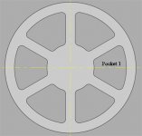
While milling a series of 6 pocket in a polar array, the machine alarms out with this error: "Compensation interference 0 0".
The roughing passes goes fine but when doing the outside finish pass it alarms out.
8mm endmill. Corners are 4.1mm radius.
As usual the manual is of no use: Correct the program...
 
Double check your drawing and make sure every corner is indeed R4.1mm. You just never know. Sometimes on a mill of mine with close calls in comp, Ive had to shrink my tool radius offset ever so slightly. If that messes with your size, you might be able to bring it back with a wear offset setting. Not sure if you could outsmart the control like that or not.

Then again... a lot of times when the control says "Correct the program"... it's right.
 
After Roughing, turn off cutter compensation and move the spindle centerline to a point that is more than End Mill Radius value away from the Roughing Pass Profile (maybe 4.1MM). Begin the first cutter compensated move toward start of Finish Pass from there. Also, next move after Finish Pass (cutter comp off) should be more than End Mill Radius value away from the Finish Pass Profile (maybe 4.1MM).
 
Thank you to both of you ! :)
13engines: You were spot on: I had modified only one of the pockets in the drawing, and while picking coordinates I used a different pocket with radius R=3,1mm.

That led me to another problem:
I had this initially programmed as XY-movements, but there was not enough Y-stroke to do the pockets at the top and bottom. So I changed the program to XC-movements. That works fine but it leaves some serious artifacts on the outer wall of the pocket (where the X-axis reverses I assume). Don't know what the issue is with that ?
So I am back to XY-movements. I want to do the first pocket straddling the X-axis, then I want to copy it in C, so that the C-axis indexes 60 degrees and then does the same pocket in the same place (but in a different place on the workpiece). I thought it was just a matter of copying the milling process and replacing the C0 line (marked in red) with C60 , C120 , C180 etc but that doesn't work. I assume the machine can put on the brake at C0 but other positions need the C-axis engaged. Anyone want to modify the code ?
Ideally I would use some macro or something to do this so I don't have to copy the whole code 6 times. If that is easy enough I would be happy to do that if anyone wants to do the code. Even more ideally I would get some proper toolpaths made as I have predrilled the pockets with a 24,5mm U drill and now it does the roughing of that all over. It seems auto area doesn't work while milling.

(P1, ENDMILL, 8.000, T707)
G0M5
M69
G98G17M45
G28H0
G54
G0T0707
M8
G97S200M13
S8000
G0Z6.
X160.
C0
M68
G0X85.295Y.141
Z1.
Z3.
G1X99.049Y5.137Z1.F1300.
G2X70.573Y4.391I-6.877J-4.996
X70.573Y4.391Z-2.I7.361J-4.25F3000.
....


PocketMilling.jpg
 
Hello Panza,

Glad to have helped you figure out the problem. Usually turns out that the machine control is right more then it's wrong.

I have a lot of mill programming experience but am still a complete newb on lathes. Yet I can visualize how to do this part easily with X and C and of course Z if you need it. EDIT: I re-read your post and see you're having thoughts along the same idea I list below.

First what I might do is drill out all the corners with a slightly under-size drill. That or an oversize one shifted slightly as to not touch the finished profile. If this is production I would only drill out a single starting corner in each separate work areas.

I would position the tool over the feature area's corner hole you just drilled, and from that point on I would program all the milling with 100% incremental (U-W-H) movements and put those movements in a subroutine. Then all you do is position the tool in X,C and Z, and call up the subroutine. In fact if you ended your tool where you started, or even if you didn't, at the very end of your subroutine you could also include a retract to clearance plain and a new H60 (incremental 60 deg C move) and whatever other moves you'd need to get to the next start position, and simply call your subroutine with a 6 times repeat count. M98P1000L6 and as example using subroutine O1000. At the end of six repeats your tool would move one extra time to the initial start position, but it wouldn't actually do anything else from there except move the turret to clear for the next tool change. Meaning there would be a tiny amount of wasted movement after the last mill op, but so what.

That's how I would do it. But it would take me forever as my lathe speed programming skills are minimal. This could also be done super easy on a mill too.
 
Thank you again!
That was a good plan, and I even got the sub program to work.
Had problems to get the C-axis to index, but then I found an example and I had forgotten the . after the angle callout.
Now everything is fine and dandy. Improved the pocket milling cycle some too, so now the actual cycle time is inline with the price.
In the manual it seemed like it was enough to have the subprogram name in the first block but for me it didn't work until the actual program file name was "100".

Here is how I did the main program part of is:

G0G53X0Z-250.
G54
G0Y0
M69
G98G17M45
G28H0
G00 T0707
M98 P100
G0 C60.0
M98 P100
G0 C120.0
M98 P100
G0 C180.0
M98 P100
G0 C240.0
M98 P100
G0 C300.0
M98 P100
M46
M69
 
Good news. Looks great. But now take that G0C60.0 near the top and make it the last line before M99 in your subroutine but change it to G0H60. Then change your first M98P100 to M98P100L6, and delete everything else in the program right down to your M46. Programming efficiency at its finest.

G0G53X0Z-250.
G54
G0Y0
M69
G98G17M45
G28H0
G00 T0707
M98 P100L6
M46
M69

:-)
 
Ahh !
So that's how it's done. I was very happy when I got rid of the six instances of the whole pocket milling cycle but this is even better !
Thank you again ! I learned a lot. Even though it is usually possible to do most things with the VPS programming sometimes it is extremely cumbersome and inefficient. And this time it didn't seem possible at all.
 
Just thought I'd update this:
Maybe nobody else in the world is using the VPS programming on their Mori, but I found out the milling toolpaths it makes are not that great. When milling the pocket pictured above I first had the enter and exit set as default, which left a pretty hefty scallop in the middle of the radius on the right side of the pocket. Then I changed to tangent circle both for enter and exit. Didn't help a bit. The problem is that the enter and exit circles uses the exact same entry and exit point. When tool deflection is taken into account the scallop is just about the same as without fancy enter and exit. So I had to modify the code: I used a large tangent circle (R=50) and put the entry point at -5Y and the exit at +5Y. That left a beautiful finish. If I am going to make more of these parts I am going to modify the roughing toolpath too as it makes a lot of overlapping moves. The last problem I had was that the endmill lasted only 3 parts (18 pockets, in 1018 or similar) and that was with a 16mm pre-hole. I ran 220m/min and 0,04mm feed / tooth as per sandvik recomendations. That isn't a problem in itself but the endmill was $100+ so it eats all of the margin. 8mm diameter and 30mm depth of cut.
 
... as per sandvik recomendations.
My experience with Sandvik recommendations was that they kept Coast Tool in prime rib. Certainly made good production numbers but the tool costs ate me alive.

I dropped way back especially on speeds and graduated from $.19/box Kraft macaroni and cheese the next month.

In fact, this is going to be anathema to some people but I saved even more money by going to cheap generic inserts for a lot of operations, especially roughing. Lots of times it was cheaper to throw a junky insert away than pay big bucks for one that lasted a little longer.

About your program, that's why I like manual programming :) Agreed, lots of parts won't work that way but for simple stuff, does a good job.
 
Hello Panza,

Wow, prices seem a lot different in your part of the world. Over $100 for an 8mm end mill is easily 3 times what I'd have to pay. I hope that thing is coated in gold. Or at least ALTIN.

I can''t determine for sure your final depth of cut. All I see is 6mm depth. Using a 30mm DOC end mill for this is likely one part of your problem. Generally try to use the absolute shortest flute length and tool stick-out you can get away with. Diameter to stick-out ratio is thee main determining factor against vibration, potential max feed rate, and about every other parameter a cutting operation needs to worry about. Even almost imperceptible vibration can kill carbide tools long before they're due. I believe live tooling on lathes is no match to a mill along those lines. My take anyway.

Proper application of coolant on carbide in steel can also make a big difference. Even no coolant can help sometimes. There are those who swear by no coolant carbide use. I've tried with and without and have found I get better tool life with coolant. All my milling machines have programmable coolant nozzles, even dual nozzles on one, so that might be part of the reason it works so well. Sadly programmable coolant nozzles on a lathe isn't a thing you can get. I know... I tried.

I have two Mori Seiki's. Neither has VPS. I'm also a fan of manual programming. That is with CAM riding shotgun.
 
Maybe I'll try lower surface speed next time. Or it might be better to do it differently altogether? I could do it in two passes with an endmill that only has 16mm long flutes. I don't know if I could run twice as much feed that way ? The endmill would need to be relived up tp 30mm..
Now I roughed it all in one pass with 0,9mm stepover. Coolant delivery could be improved too. I had good coolant flow to the mill 90% of the time but the remaining 10 was not good.


Back
Top