What's new
What's new

MAHO MH400E retrofit to Linuxcnc

asah

Plastic
Joined
Dec 2, 2013
Location
Cotati, CA
Starting a new thread here to share my build progress I have been sharing in the "fix your maho" thread.

I have a 1986 MH400E which was retrofitted with a 1991 phillips 432 control at some point. The control died a few months into owning it. I could have fixed it, but I was tired of handwriting GCode to use the thing. Very limiting for a control. The serial interface was buggy and slow... etc. So last week I pulled the plug on it. snipped the IO ribbon cables and plugged them into my Mesa IO boards and away I went.

Background on the machine and hardware I am using:

The mill is from the era of the fixed speed spindle and 18 speed gearbox, which is one of my bigger challenges ahead.
I am using the following mesa hardware:
5i23 - FPGA board
7i70 - 48 opto isolated outputs
7i70 - 48 opto isolated inputs
7i44 - 8 port smart serial card
7i52 - 6 port quadrature card
7i83 - 6 port analog servo interface card.

You could do all that I am doing with a much more minimal setup such as one of the 5i25/6i25 kits, but I have other plans for all this IO. =)

Yesterday I got to the point of full closed loop control (save some PID tuning) but several projects remain to finish the retrofit.

Spindle / Gearbox
Automatic lubrication
Tool Changer
remote pendant and control surface integration
Integrating computer into the old 432 location.
Touchscreen?
etc...

I'll post photos from the build and progress as I progress.

Overall things have been pretty straightforward, working through the schematics, learning them well, and progressing in small stages.
 
I had one of the exe channels blow on the EXE board when I shorted some power onto it I believe. A friend helped isolate the blown chip (the 422 driver) and I replaced it today. I now have full 3 axes of feedback and have run the spiral gcode file!

On the spindle / gearbox front I was able to run the spindle and I made a small control panel in Linuxcnc to run the gearbox controls. I have successfully controlled each of the motors and the tip right and left controls which help the shifting process by slightly nudging the spindle left and right to lessen the gear binding. I still need to get the gear changing controls buttoned up so it is user friendly, but it works for now.

I have a strange "chirping" problem on the spindle when it is changing from star to delta winding on the starter. The contactors try and engage for the delta circuit, but are not able to for some reason. Trys every few seconds and sounds like something is grinding in the gearbox, but you can see the contactors "bouncing" in the cabinet. Once things are warmed up (perhaps the spindle motor?) it will switch to delta fine. This shouldn't be a problem when I move to the VFD for the spindle, but for now it is somewhat grating. Anyone else see this?

Another issue I identified on my machine was that someone, somewhen replaced the IO ribbon cables on this machine. But instead of using 40 conductor ribbon cables with the 40 pin connectors they used 37 conductor. This SEEMS fine when you look at the schematics which only show 37 conductors in use, but what happens is because the ribbon is interlaced top and bottom, you really need the full 40 pins. This means that two pins are not connected which should be. One is pin 19 (a gear identification pin) and the other is the coolant enable pin. This may be why my coolant pump is missing, its contactor has been ripped apart and the coolant pump was replaced with a 110v aftermarket pump with a foot switch. All from one missing io pin. Hmmm coolant pump not working... can't figure it out... replace it! I think it would be nice to have gcode control over that pump... ill connect it back when I have some time. Anyway. I bought some 40 conductor cable and idc connectors so I should be able to solve it.

Pics next.
 
IO connections to the 28X1 and 28X2 relay boards.

Here is how I connected the IO. You need to make sure you alternate front and back rows with each wire as the IDC connectors are alternating pins for top and bottom rows. I used the front row on the mesa for the first (odd pins) and the back for the evens. Hopefully that makes sense in this photo. I just plugged them all in to ease debugging and working on them. This is one reason to use a 48 port card. =) I will really only need a quarter of the IO once I get everything worked out. I recommend this approach for personal sanity, but certainly doable other ways.

IO_001.jpg

The bottom card is the analog out card driving the servos. All three of these cards are powered from 24V avail inside the cab.
 
EXE board hacking

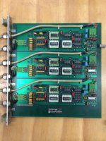
Here is the fine work of Dr Johannes Heidenhain. Three channels of pulse shaping goodness.
Screen Shot 2013-12-23 at 7.40.53 PM.jpg
EXE_BOARD.jpg

I hacked into the output of the EXE board pictured below

EXE_HACK.jpg

Black and yellow are the quadrature outputs.
Red appears to be index (homing), but I haven't worked on homing yet.

Make sure you attach ground / common 0V to your quadrature reading card. I believe these signals are supposed to be differential(based on the line driver chip on the EXE), but I have not gone in and found the corresponding differential pairs. They are not listed this way in my schematics so I have them hooked up in TTL mode, and this is working fine for me.
 
asah
Thanks for posting all of this, great thread. I was interested in buying one of the small Maho a few years ago from a PM member but couldn't get a few basic questions answered the most important being the price. More photos and video please
Andy
 
Yep that was me.
I got the gearbox pretty sorted. I wrote a python component to handle the switching.

I have all systems working under linuxcnc under 3 phase power. This includes gear changing, spindle, tool change, axis control.

Next step is the bigger step of getting everything under single phase. This involved the fitting of the 3 fanuc servos I have purchased. Z is a drop in to the existing bolts, but I am going to have to make adaptors for the X and Y to fit these servos. (I have swapped the Y and Z in the control, so now it is setup like a vertical not a horizontal)

Wow! You have made all of that work quite fast then. I guess programing must be one of your strong points then. For my part the programming is probably my weakest point, so this part will be the hardest one for me. But it is what I'm about to do on my machine. I have the computer all set up now and will start the actual hooking up and testing now soon, when I get the time that is.

I'm assuming your ATC is the same 20 tools umbrella style ATC as I have on my mill. Would you be willing to share the logic files you made for it to work please?

I'm not using LinuxCNC for now (although I have Mesa hardware to do it). But I'm guessing the logic will be possible to convert. The important thing is to have the logics worked out correctly, which is not straight forward. At least not to me.
As far as I know the hardest part is to have all the safety measures in place, and it's this part that I was hoping not to have to do all from scratch. And from my little experience when trying to make my mill work there are a lot of things that could go wrong during a tool change.
So the logic behind this will therefore be rather complicated if all possible errors are to be taken in to account. From the error list of the Philips 432 controller there are quite a few error messages dealing with the ATC. So I'm guessing this also means there are a lot of logics behind all of these error messages.

In fact the ATC and all logic functions needed on the error checking is the one thing I'm expecting to be the hardest and most complicated part of the retrofitting altogether. It's also why I never even considered using Mach3 for the retrofit, it lacks the ability to do this (if you aren't a programmer capable of making your own plugins to make it happen that is).
And since we are now several people doing a retrofit of this class of ATC on Mahos I suggest helping each other’s here.

In what degree are your logics checking for error at this stage? And are you planning on putting some effort in to this or just make the basics work and then let it time out and fail if something isn't working? I don't recommend this as I'm sure things will break. With my mill came at least a couple of broken off fingers for the ATC in the box with spare parts. So I'm quite sure it pays off to putt some effort in to getting the fault logics of the ATC as good as possible.

I remember one really annoying thing from the 432 controller. If you failed during a tool change it assumed there is a tool in the changer. And since it's not possible to start a tool change mid process the only solution was to go inn and erase parts of memory by changing parameters and restarting the whole machine. An annoying and lengthy process that will be great not to have to do after the retrofit. So I'd like to have the possibility to sit by the control panel and override each hydraulic function. This should be normally hidden since it could be quite destructive if not used properly. But it would be convenient to be able to intervene in the tool changing process if it fails, and not have to do it like it is now where you have to manually engage the hydraulic functions on the valves in order to reset the ATC, and then erase the memory functions and restart the machine from scratch after that. I'm sure modern machines have good implementations of this. So copying the whole process from a modern machine would probably be the best idea. Would this be possible?


I also think I will exchange the Y and Z axis to make it behave like a vertical mill like you have done.

For the EXE cards I have found there are several versions. They all seem to do basically the same thing. But some of them have differential outputs while others don’t. The ones I have do have differential outputs, and only use 5V supply. But I know Maho made 12V available on the connector, so some of these cards might also need this. It shouldn't be any problems to use the single ended ones though. As long as you do the grounding properly and don't make ground loops and such they should work just fine.

BTW, some pictures of your machine would be nice :D!

Anders
 
Umm we are going to need a video.. :) Great work!

sam

Yep that was me.
I got the gearbox pretty sorted. I wrote a python component to handle the switching.

I have all systems working under linuxcnc under 3 phase power. This includes gear changing, spindle, tool change, axis control.

Next step is the bigger step of getting everything under single phase. This involved the fitting of the 3 fanuc servos I have purchased. Z is a drop in to the existing bolts, but I am going to have to make adaptors for the X and Y to fit these servos. (I have swapped the Y and Z in the control, so now it is setup like a vertical not a horizontal)
 
Wow! You have made all of that work quite fast then. I guess programing must be one of your strong points then. For my part the programming is probably my weakest point, so this part will be the hardest one for me. But it is what I'm about to do on my machine. I have the computer all set up now and will start the actual hooking up and testing now soon, when I get the time that is.

Sorry to disappoint, but I only have a 400E which sadly has no ATC. I have hydraulic tool clamp/unclamp, and that is what I meant when I say I have tool change working.
I would love to have a larger machine someday which has an ATC. I have a small scara robot I will likely put into tool changer duty when I get all this situated together and running.

I also think I will exchange the Y and Z axis to make it behave like a vertical mill like you have done.

For the EXE cards I have found there are several versions. They all seem to do basically the same thing. But some of them have differential outputs while others don’t. The ones I have do have differential outputs, and only use 5V supply. But I know Maho made 12V available on the connector, so some of these cards might also need this. It shouldn't be any problems to use the single ended ones though. As long as you do the grounding properly and don't make ground loops and such they should work just fine.

BTW, some pictures of your machine would be nice :D!

Anders

Here are a couple of photos of it on the first day off the truck

IMG_2211.jpgIMG_2212.jpg
 
asah

could you please list:

servo motors model and voltage

encoder specifications

servo drives/amplifier specifications

computer type and specs with operating system

thanks

jh


Hi there. Good questions.

Computer is a very simple shuttle XPC from perhaps 5 years ago. It has a celeron processor and 2 gig ram.
I am running the servo loop at 5khz which is pretty good for such a low spec machine.

Running linuxcnc on ubuntu10.04 from the 32 bit system image off of linuxcnc.org download

Really pretty simple to get the installation working. The harder bits are wrapping your head around the different parts of linuxcnc, but there is great help on IRC and on their site, so very approachable I would say.

I am happy to share configs and experience with other mahoites.

The new fanuc servos I am putting in are ebay specials, 2 x 5F series (6 Nm, 127V, 3000rpm) (certainly salvaged off a robot as they have brakes and 2000 count absolute encoders) for the x and y axes, and a 5 series with a brake for the Z (5.9 Nm, 110V, 2000rpm). I have not confirmed these will work on this thing, so don't quote me on it yet. I am using Mesa 8i20 servo amps mesanet.com . Ill certainly post more about this phase as I progress through it.

Asa
 
finally spun all the motors today!

Got my new mounting brackets and everything back a few weeks ago and mounted them up to the machine. Been spending some time working through each motor / encoder and getting the baseline setup going on a bench so I have some rough starting point when I am spinning the leadscrews.

Going to hook up the Y axis today. =)
 
Y axis working. Tuning the mesa 8i20 torque loop currently. I changed out my lame EXE hacks from above and have the cable going directly into the quadrature card from the EXE board.(I'll post some pics when I get all the axes converted over).

I haven't figured out exactly how I am going to incorporate the glass scales as I am being coached others have had issues closing the loop around glass scale position when there is mechanical backlash present. Success has been reported using the scales only to influence the integral term, as well as others going with a cascaded outer position loop and inner velocity->torque loop. Ill try them and report my findings.

The scales are Heidenhain LS 403, which I understand come in 20um and 10um gratings. I don't know the interpolation on the EXE board, I have seen reference to 5x and 25x versions which would give me a final quadrature resolution of 4um(20um grating) or 2um(10um grating) at 5x and 0.8um(20um grating) or 0.4um(10um grating) at 25x. This along with the 4x I get off of the quadrature edge detection gives me quite a few permutations of possible scales. Anyone been through this with these scales and settled down on a number for counts per mm? Anders?
 
Torque mode tune is going along ok. I have a decent tune for now, will certainly have to return to it when I am actually cutting.

The biggest issue seems to be that I have about 10% mechanical backlash in the motor drive to the axis. I have not located the source of the lash, but it looks to be in the ballscrew assembly. This causes bad following error at the beginning of any change of direction which can't really be tuned out. I reduced the axis acceleration to 250mm/S^2 and am able to get a decent tune that will allow me to progress to the other axes. If anyone has any backlash adjustment ideas for the Y axis (Z axis originally) please let me know. I noticed there is a preload spring it seems in the X axis on the large sprocket, that does not seem to have as much travel in the Y.

I upped my servo rate to 5khz, added some FF2 and FF1. I'll share my configs on bitbucket soon if anyone is interested. I couldn't find a good example of an 8i20 tuned for torque mode so perhaps that will help someone else.

I have not incorporated the glass scales yet, I started to get noise issues on the B channel. I think I really should take the differential leads from the differential driver chip, and not rely on TTL. I am going to mount the mesa boards inside the cabinet where they will be very close and so the run will be much shorter, perhaps this will help.

I moved on to the X axis:

Mounted up my X axis Fanuc Servo on my new mounting plate. Its not perfect, but it will get the mill up so it can make its own replacement. Pictures soon.

Then I spent a loooonnng time ripping apart and soldering up the signal and power cables for the X axis. Only have to do that a few more times. =)

I had an issue with the Willey Vogel central lubrication system not pumping, and spent some time learning about the IG38 timer etc. The fault light was on and it wouldn't pump even though I was powering it directly (with both the 110vac and 24vdc it needs). It turns out the WS circuit is the oil level sensor. I was right at the minimum and so it shut off. It would be nice to get that information back to the control, so I plan on routing that signal in. Popped one of the WS leads off and the pump fired up. Nice to have lubrication again. Might help the backlash... a little. =)
 
There are different versions of EXE cards (or boxes as they are really), some with fixed interpolation rates, others with variable.

The scale used on my mill originally is the exact same as you have, LS 403. And the interpolators that is used originally is the ones with 5x. This is what's found in the majority of EXE cards available on fleabay. And the cheapest ones. I think you can have them for less than $50, possibly as low as $30 a piece, don't remember exactly except it was very cheap! This is what's in my mill originally, and it has full 1 um resolution on the DRO. And they output a square wave of 1 kHz when moved 1 mm/s. I got some of the higher resolution ones as well, but when I tried to use it with my Camsoft setup it was actually worse performing! And it didn't accept having a factor of 5 higher resolution on one of the axes compared to the others......

So I got 3 of the cheap type (EXE 602 wasn't it? See my previous post about it) and will be using them. And that is what I recommend you use as well.
And I recommend you try to get some with cables so you can interface to them easily (some think of preserving the attaching connector when selling them, a big pluss). The ones I bought came with the output cablesm, which is the ones I needed. It's so much easier when you have the complete sets of connectors. One side of the box should have the connector to connect directly to your scales, so you don't need that end (they use different connectors on input and output so you don't connect them the wrong way around). The output should go to your Mesa hardware. And using the original connectors is really recommended. And the connectors are absolutely fantastic quality! They would most certainly cost more than the whole EXE card does if you were to get them new. So even if you have to spend a few extra bucks to get the wires you should get them. That is if you don't already have them.....

I replaced the connectors on the other end to be compatible with what's used on the 432 controller, for ease of swapping controllers. This is 15 pin d-sub. They came with 9 pin d-sub connectors.

And they have differential outputs that interfaces directly to the Mesa cards. No need to hack on to the card like you describe...... And the Mesa cards can provide the power needed (+5V only needed) as well. It all works very well directly with Mesa hardware without any need for adaptations. This I have already tested.

Anders
 
Good info thanks. I have a 3 axis EXE board ( pics above). I don't see enough wires in the connector to be true differential though. There is only a b z 5v 12v and 0v
 
Ah yes, you already have an EXE card. Yes, some of them are single ended only. It seems to be the older ones who use single ended outputs mostly.

The original one in my controller is also single ended. I switched controller (the whole unit with all cards) with a friend’s 800 to make mine work (and his worked with mine, which my machine didn't for some reason). So now my controller has one which is differential because the EXE card in that controller was a newer one.

It looks newer with more components and more sophisticated SMD components on it than the one from my mill. Yours look even simpler than my original one, with older design and less components. But as you say, Heidenhain is a quality brand and their stuff is very reliable. I wouldn't worry too much about using it as it is now.

No worries though, single ended works equally well. And you should have the same resolution on these as I have on mine. My will have been run long and hard (as was clearly visible on the machine when I got it), and I have no reason to believe parts of the encoder scales have been replaced. So this is a really reliable and trustworthy system. There is no reason you should consider replacing it. Particularly since you already have it in there. Fitting in a new system is in fact quite a lot of work, in particular if it needs to be adapted.

Or alternatively you could get some EXE 602 units of fleabay. They are differential outputs, and will read your LS 403 scales to get you the same resolution as you already have. But in real life there will be no difference. Just keep the signal wires short and you should be ok.

One thing that might be different on the newer is the speed they can operate on. That obviously depend on the speed you want to run it at. You should take a look at that if you plan on running this machine at considerably higher speeds than it was originally made for. The general rule is that the newer units have higher speed capabilities. And yours is so old speed might be an issue worth looking in to. Just as a precaution that is.


Anders
 
Good thing you are able to get your 8i20 drives to work.

I bought one of those with the intention to test out if they will be able to replace my Indramat drives. They should be able to drive my servos, given I provide new feedback. I have rotary encoders I can put on there. 2500 ppr ones which should give 10000 counts in quadrature.

Now the problem is the dual loop we create. I haven't figured out how to do dual loop control in LinuxCNC. I have read it should be possible, but I'm not sure how to configure it to do that. Right now I'm trying to get my head around making a config made by Pncconf work (except that I'm waiting for new hardware since I blew up my Mesa cards). I'm no programmer, which is clearly a disadvantage with LCNC. It is clearly written only with programmers in mind, so that's the hardest part for me when it comes to this retrofit.

Anyway, I also have a different (and WAY more expensive) controller I intended to use on my Maho, a Galil controller with CamSoft software. For reasons you can read about in other places I put that on the shelf for a while.
Anyway, I understand your problems with dual control loops, and that you have a considerable amount of backlash. In this regard Galil have a video tutorial about their way of solving it. Dr Taub at Galil really seems to know what he is talking about when it comes to controllers. Which is probably why they are as successful as they are I guess. Anyway, the video is in fact a quite general video on how to handle control of systems with backlash in them by using dual loop control. The key is to have one encoder on the load (your HH scales will do as that) and one on the motor (your motors already have encoders for that). I guess it's a known way to do it, but I think the video explains it quite good. And it should be the key to solving your backlash problems.
The video is here: Tutorials - Galil: We Move The World (I hope it's ok to post a link to this video?).
I’m not sure how LCNC is implementing dual loop, and if it’s possible to have control on how it’s done. If it’s already available as described in the video there might not be a need to do much configuration. It’s a known way to do it. The question is whether LCNC have implemented it in the present versions. Not sure, but I will try to find out when I get to that point (if you don’t beat me to it…).

It will be how I'd like to do it when I try to use the 8i20 cards as well, so I'd be really interested in your config files. Having files which already works is always a good thing. It could be a good idea to post some details about your machine on their forum as well? And that might probably be the best place to post your configs. There will be more people looking for configs there.

BTW, the new GUI's they have made for LCNC looks quite a lot better than the old ones (and way better than what is presently available for my CamSoft software even if that is high cost software.....). So I hope you also consider implementing one of them. I like the one called gmoccapy. It seems to be the one which is most up to date with what a professional controller will provide. The problem for me is that as it is now there is no way to get that new GUI with the configuration tool for Mesa hardware. It's also well maintained by one single person, whom seems to be quite eager to make it do what users ask of him.

Have you made the digital I/O work yet? I intend to keep the rest of the machine in almost original shape. After all it works kind of ok. And redoing it would be a major undertaking, something I don't think will be worth it. But it will need some of the I/O pins set to start the machine. You could do as I did on my previous tests, hardwire it to high, to be able to start the system. But it is a good idea to wire the e-stop chain as it was meant to when doing testing as well.

Any plans to do a more thorough check to see where the backlash is coming from? My system doesn’t seem to have much of it, so I’m kind of curious to know why you have as much as you describe in your mill. Do you know if your mill has long (in effect two in series, preloaded against each other) ball screws on it?
Or could the balls be worn? I have tested replacing balls, and if you have the screw assembly out it’s not as hard as most people will have you believe to replace them. It might be worth looking in to. New screws of the quality and size you need will cost you…..

Anders


Back
Top