What's new
What's new

Lower head for wire EDM design

Obi

Plastic
Joined
Nov 25, 2020
We are want to design own automatic wire threading. So no questions about upper head its all understand. What about lower head - what reasons the wire curve for 90 deg a went to the back of the machine (its about 1 meter). May be there is some horizontal flow force water or air?
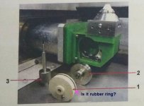
Agie/charmille is different from everyone else. They have active gripper rollers inside lower head. Others producer have only passive roller in lower head. Right ? Please help me for understand process.
 

Attachments

  • awt1.jpg
    awt1.jpg
    77.7 KB · Views: 54
  • accut5.jpg
    accut5.jpg
    39.6 KB · Views: 61
The threading cycle starts:

1: The water jet on the top head

2: The water jet on the lower head, which turns a paddle wheel, that rotates a ceramic wheel

3: wire starts feeding from the top , until a sensor at the back of the machine detects that the wire is threaded.
 
2: The water jet on the lower head, which turns a paddle wheel, that rotates a ceramic wheel

Please more information about paddle wheel. Paddle wheel work as active and drive from flow of water?
What for ceramic wheel? What force push the wire to evacuation tube to back of machine? Force of rotate wheel or pushing from upper head mechanism.
In attachment documentation from lower head ONA. There are really 2 wheels, both named as passive wheels. On ceramic wheel there is black element like rubber ring?
 

Attachments

  • Image1.jpg
    Image1.jpg
    43.5 KB · Views: 64
  • ona2.jpg
    ona2.jpg
    82.9 KB · Views: 48
The good side of the charmilles design, only need to get the wire slightly past the lower guide and it is threaded. On a sodick, need to get the wire all the way to back of machine to engage the threading
 
My experience is with a Makino CNC edm .

The lower head has:

Static shaft
(2) bearings
(1) ceramic wheel That has (3) holes equally spaced.
(2) plastic end cover....(1) of which is the paddle wheel.
(3) o rings (1) plastic cover has (2) o rings . (1) for shaft

The o rings are sized to keep the dielectric / flushing fluid out of The bearings .

Bolts for covers have o rings sized to bolts with washers.

(2) water jets (1) spins the paddle (1) pushes the wire toward the back of the machine

The rear of the machine uses pinch rollers...
 
Correct me if I'm wrong : Ceramic wheel rotate due to flow to paddle wheel. Ceramic wheel have small gap so it press the wire and push it in to evacuation tube. Is it right ? May be you have any photo video or shots from service manual


Back
Top