What's new
What's new

Need help

thor232

Plastic
Joined
Aug 25, 2017
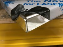
Hey guys am new in the sheet metal fabrication world and need your help with the problem am having i designed a sheet metal enclosure in solidworks and put that design to laser cutting and but the problem is i have used the closed corners tool but when i sent laser cut sheets to press bending(manual one ) there i always get a huge gap on the corner i played around with the bending radius but nothing seems to get it right any advice would be great thanks and here are the pictures if the bending parts
7545d96e42f4e35cd4ac9079e8b7aecf.jpg
92e233c3689d5c2bb28696ae5bf4c01f.jpg


Sent from my SM-G935K using Tapatalk
 
It looks like you have a good enough bender which goes to tolerance of +/- 5 degrees.

Ways to fix that once you get it...
Hammer
Channel locks
Bar clamps

Sent from my SM-G960U using Tapatalk
 
Thanks for the reply but i tried 3 different press breaks they result is the same is there any way of preventing the problem from occurring the gaps are very wide
b268da07c8417e87ec2df7b7f1b2f1c1.jpg
ebb35de3f42cfcc265fd2ce16ed3ef87.jpg
961d7d75b8aac00c7a49d3212e91136e.jpg


Sent from my SM-G935K using Tapatalk
 
my tip to you might be an odd one, but watch some manufacturing videos on youtube, you may see what they are doing differently. My guess to a fix is slight adjustments, and tinkering with scraps will get you there. Nearly every machine has a quirk, your job is to overcome it or use it to your advantage. Adam Booth (abom79 on youtube) recently toured strongholds factory and got some good footage of their process for making products similar to yours. good luck.
 
my tip to you might be an odd one, but watch some manufacturing videos on youtube, you may see what they are doing differently. My guess to a fix is slight adjustments, and tinkering with scraps will get you there. Nearly every machine has a quirk, your job is to overcome it or use it to your advantage. Adam Booth (abom79 on youtube) recently toured strongholds factory and got some good footage of their process for making products similar to yours. good luck.
Thanks i will check it out

Sent from my SM-G935K using Tapatalk
 
I'm not really seeing the problem.

It appears that you would just pinch the legs closed to touch on the corner, and weld it shut.

I doo see you corner relief (on the white piece) looks to be in the wrong place.

The bare steel one looks like a small tap with a hammer will pull it right in, put a tack there, and work your way down the seam.
Hey Doug i was thinking of welding it shut but there will be a batch order so i will increase the production process meaning increased cost i don't know where am getting it wrong but i know it's a simple mistake may its from the design bend radius or something is there any way i could redesign the box to get better edge corners

Sent from my SM-G935K using Tapatalk
 
From the 3rd picture, it looks like about 3x the bend length up there is a little wave in the bottom edge. That is caused from over bending the 4th bend and it smashes into the previous side and bends it out. I could be wrong as well since its dirty.

The bend relief cut is also in the wrong spot, it needs to be directly in the bend.

Some steels depending on where you get it from are made from junk and just wont bend perfectly. Too much spring back.

It would probably just be best to build a jig to use toggle clamps to quickly push the corners together.

Sent from my SM-G960U using Tapatalk
 
Hey Doug i was thinking of welding it shut but there will be a batch order so i will increase the production process meaning increased cost i don't know where am getting it wrong but i know it's a simple mistake may its from the design bend radius or something is there any way i could redesign the box to get better edge corners

Sent from my SM-G935K using Tapatalk

Oh !

Now I see.

You wanted it as you've pictured it, sans weld.

but correctly at a right angle and a sharp corner.

I've been known to make a fast pass downhill with 1/8" 7014.

then I got a mig welder with .023 wire and gas.
 
Thor, have you established that you have the correct bend radius and K-factor or Bend Deduction in Solidworks such that if you bend a U-shape for example you get exactly the width and leg length you expect? This is a tedious project you can do, I did it waterjetting and bending L shapes in every material in each thickness and with different lower dies, but the result is you should be within say .005" for each bend, so I'm inside .010" for the width of my U-shapes. I got there by making a set of gauges to measure the inside radii of the bends and then calculating K-factors. Having done that, I've had decent success with the closed corner feature on Solidworks. We actually have a pencil case project I use to teach engineering students about sheet metal and they can get the corners closed. We have an ATEK B412 by the way, with a CNC back gauge.
 
First question would be: Ignoring the corners, are the outside dimensions of the parts coming out correct? If so, your corner notches are cut wrong. If not, skip the next couple paragraphs.

I don't use solidworks, so I'm unfamiliar with anything pertaining to it, but it's very easy to look at the parts and see what is wrong - hopefully you're familiar enough with the program to be able to communicate the needed changes to it.

I'm going to assume your dimensions are correct, given that you've asked about closing up the gap, as opposed to asking about how to fix the finished part dimensions.

Looking at picture one, as well as the picture with the white painted sheet, it's clear that the parts are notched back too far - that's not something that could be hammered or clamped back. You need to measure whatever gap you have, and decrease that amount from the notch cutout size (ie, if in one direction, you measure a 1/8" gap, you need the notch to be 1/8" smaller than it currently is).

What's usually a good rule of thumb for me for notch size is the outside height of the flange, minus the material thickness (3" flange on 11 gauge material would use a 2 7/8" notch).

There also seems to be angular issues. Those are probably only 1-2 degrees off, but on a flange that large on material that thin, a degree or two is significant. I can't even imagine trying to work with +/- 5 degrees.:eek: That's not something we can help with, you or whoever is bending those will have to clean that up at the machine.

On the parts with the return bend in one direction, and merely a single flange on the other, bend the single flanges first, then turn the part to hit the bends with the return flange. If you bend the return sides first, the single sides will collide with them when overbending to compensate for springback. If you do the return flanges last, the flange can overbend into the space between the single flanges, then spring back to the proper angle. Furthermore, this saves you from having to use horn tooling to get into the corners.


If it turns out that the part dimensions are wrong, it likely has to do with solidworks not having the right radius listed. You'll need to do as rcoope mentioned, and measure the radius that whatever tooling you are using gives you on each material thickness you use, and work with that. My understanding is that solidworks is capable of doing the K-factor calcs (and that will probably fix the gaps, and place the clearance hole correctly), but if not, the formulas are readily available online to calculate your unfolded blank size, and then you can easily figure the notch cuts using the method I mentioned above.
 
Thor, have you established that you have the correct bend radius and K-factor or Bend Deduction in Solidworks such that if you bend a U-shape for example you get exactly the width and leg length you expect? This is a tedious project you can do, I did it waterjetting and bending L shapes in every material in each thickness and with different lower dies, but the result is you should be within say .005" for each bend, so I'm inside .010" for the width of my U-shapes. I got there by making a set of gauges to measure the inside radii of the bends and then calculating K-factors. Having done that, I've had decent success with the closed corner feature on Solidworks. We actually have a pencil case project I use to teach engineering students about sheet metal and they can get the corners closed. We have an ATEK B412 by the way, with a CNC back gauge.
Hey recoope thanks i think your methods can be time taking but very accurate to this and future works i don't have the press break machine on the shop so i need to send the lasercuted part to another workshop thats why hesitated to use your idea but its better to take my time now and fix it for further design thanks

Sent from my SM-G935K using Tapatalk
 
First question would be: Ignoring the corners, are the outside dimensions of the parts coming out correct? If so, your corner notches are cut wrong. If not, skip the next couple paragraphs.

I don't use solidworks, so I'm unfamiliar with anything pertaining to it, but it's very easy to look at the parts and see what is wrong - hopefully you're familiar enough with the program to be able to communicate the needed changes to it.

I'm going to assume your dimensions are correct, given that you've asked about closing up the gap, as opposed to asking about how to fix the finished part dimensions.

Looking at picture one, as well as the picture with the white painted sheet, it's clear that the parts are notched back too far - that's not something that could be hammered or clamped back. You need to measure whatever gap you have, and decrease that amount from the notch cutout size (ie, if in one direction, you measure a 1/8" gap, you need the notch to be 1/8" smaller than it currently is).

What's usually a good rule of thumb for me for notch size is the outside height of the flange, minus the material thickness (3" flange on 11 gauge material would use a 2 7/8" notch).

There also seems to be angular issues. Those are probably only 1-2 degrees off, but on a flange that large on material that thin, a degree or two is significant. I can't even imagine trying to work with +/- 5 degrees.:eek: That's not something we can help with, you or whoever is bending those will have to clean that up at the machine.

On the parts with the return bend in one direction, and merely a single flange on the other, bend the single flanges first, then turn the part to hit the bends with the return flange. If you bend the return sides first, the single sides will collide with them when overbending to compensate for springback. If you do the return flanges last, the flange can overbend into the space between the single flanges, then spring back to the proper angle. Furthermore, this saves you from having to use horn tooling to get into the corners.


If it turns out that the part dimensions are wrong, it likely has to do with solidworks not having the right radius listed. You'll need to do as rcoope mentioned, and measure the radius that whatever tooling you are using gives you on each material thickness you use, and work with that. My understanding is that solidworks is capable of doing the K-factor calcs (and that will probably fix the gaps, and place the clearance hole correctly), but if not, the formulas are readily available online to calculate your unfolded blank size, and then you can easily figure the notch cuts using the method I mentioned above.
Some fruitfull information you taught me thanks but do you suggest any video i should be watching to fully understand thanks

Sent from my SM-G935K using Tapatalk
 
Some fruitfull information you taught me thanks but do you suggest any video i should be watching to fully understand thanks

Sent from my SM-G935K using Tapatalk

I don't know about any videos teaching that stuff, but there are enough knowledgeable people on here, that we should be able to walk you through it.

For starters, compare your outside finished dimensions to that of the he drawing in solid works, and report back. Let us know if the part is coming back too large, too small, or right on the money.
 
The issue is not with the Press Brake. My opinion assuming the layout is close to correct is you are using too big of a Radii on the Punch Tool and too big of an opening on the Bottom Die. Thus the Material close to the bend is binding.

Hard to tell the thickness from a picture but making a couple of assumptions here is the way we run parts 24-7 and they come out perfect every time:

No matter the thickness (12 Ga and less) use a Sharp Punch, .015R (Best Radii) up to 1/32R Max.

Bottom Die Opening and K Factor (Mild Steel only, Aluminum and Stainless are different):

.024 Thk: .236 Open, .300 K

.031 Thk: .236 Open, .340 K

.036 Thk: .236 Open, .390 K

.048 Thk: .276 Open, .390 K

.060 Thk: .315 Open, .390 K

.074 Thk: .394 Open, .365 K

.090 Thk: .394 Open, .340 K

.104 Thk: .472 Open, .325 K

.118 Thk: .551 Open, .295 K

Corner Construction:

For an inside outside corner I back the "inside Corner" off .0075-.010 (Gap after forming) and the "outside corner" the same.

This allows for the corner a little wiggle room for adjusting flange lengths to get the part to come out to print. Backing the outside corner edge off slightly keeps it from bottoming out in the bottom die which creates its own issues.

Here is a .060 #8 Stainless part formed with the corner construction listed above.

Forgot to mention the info above is using 90° Tooling and coining the bends. If you are using 86° Tooling and air bending this requires different Openings and K Factors. We are in the process of developing our 86° Tooling change over right now. The only issue we have run into is the Off-Line programming systems out there require 8 x Material Thickness for a Bottom opening which we are seeing the same issue you are having to a lesser degree. We are working with the software people and tooling people to come up with a solution where we don't have to lie to the software in most cases to get the corners the way we like them.

Good luck...
 

Attachments

  • IMG_7949.jpg
    IMG_7949.jpg
    81.6 KB · Views: 73
Thor, the thing is your Soldiworks parameters always need to reflect the press brake that is actually going to get used for the job whether its at your shop or someone else's. We have a waterjet and the Atek B412 in house so I have the parameters for that, but we also send a lot of stuff to a local laser place and they can also form and weld for us, so when they form I use their recommended parameters, and parts come out perfect every time. If the shop you are send it to doesn't know what their parameters are, then they need to get that figured out or nobodies bends are going to be good.

Are you in a situation where you have direct access to a laser but not a press brake? Also, are you in an academic research setting? If so I have professional tips on how to get academic machine shop managers to do what you want.
 
The issue is not with the Press Brake. My opinion assuming the layout is close to correct is you are using too big of a Radii on the Punch Tool and too big of an opening on the Bottom Die. Thus the Material close to the bend is binding.

Hard to tell the thickness from a picture but making a couple of assumptions here is the way we run parts 24-7 and they come out perfect every time:

No matter the thickness (12 Ga and less) use a Sharp Punch, .015R (Best Radii) up to 1/32R Max.

Bottom Die Opening and K Factor (Mild Steel only, Aluminum and Stainless are different):

.024 Thk: .236 Open, .300 K

.031 Thk: .236 Open, .340 K

.036 Thk: .236 Open, .390 K

.048 Thk: .276 Open, .390 K

.060 Thk: .315 Open, .390 K

.074 Thk: .394 Open, .365 K

.090 Thk: .394 Open, .340 K

.104 Thk: .472 Open, .325 K

.118 Thk: .551 Open, .295 K

Corner Construction:

For an inside outside corner I back the "inside Corner" off .0075-.010 (Gap after forming) and the "outside corner" the same.

This allows for the corner a little wiggle room for adjusting flange lengths to get the part to come out to print. Backing the outside corner edge off slightly keeps it from bottoming out in the bottom die which creates its own issues.

Here is a .060 #8 Stainless part formed with the corner construction listed above.

Forgot to mention the info above is using 90° Tooling and coining the bends. If you are using 86° Tooling and air bending this requires different Openings and K Factors. We are in the process of developing our 86° Tooling change over right now. The only issue we have run into is the Off-Line programming systems out there require 8 x Material Thickness for a Bottom opening which we are seeing the same issue you are having to a lesser degree. We are working with the software people and tooling people to come up with a solution where we don't have to lie to the software in most cases to get the corners the way we like them.

Good luck...
You don't know how am carving to get the smooth and clean bend as yours . And am thinking to measure the v die opening of the press break am using and the punch radius so as i can set it in my solidworks parameters can you tell me or lead me to a videos where i can see the main parts to be measured

Sent from my SM-G935K using Tapatalk

Wilson Tool has some great information: Resources | Wilson Tool International Resources

Keep in mind unless you use a 1/64 or 1/32 Radius Punch you will not get the results we achieve. Same applies to the Bottom Die opening. Not saying it cannot be done. You will not get the same results.

Here is all you need to make the measurements:

Forming 101-08 Punch & Die Measure.jpgForming 101-08 Punch & Die Measure.jpg
 
Wilson Tool has some great information: Resources | Wilson Tool International Resources

Keep in mind unless you use a 1/64 or 1/32 Radius Punch you will not get the results we achieve. Same applies to the Bottom Die opening. Not saying it cannot be done. You will not get the same results.

Here is all you need to make the measurements:

View attachment 264010View attachment 264010
Ok thanks but am curious cant i give a bit of exaggerated bend radius to make it universal to most press break i could close the corners on solidworks i know thr corner relief gap will be a bit wide but thats ok am asking because am using different workshops to bend my parts because they are not that professional in there work i need to measure all the die openings of all of them so before i do that is there any modification i could do on the software so that the bending wont need that precision

Sent from my SM-G935K using Tapatalk


Back
Top