What's new
What's new

Sheet metal roller / slip roll design

t_sheen

Plastic
Joined
Feb 2, 2016
Hi,

I'm new here and am looking for some guidance on the design of a sheet metal roller.

I am designing and manufacturing a 2 roll hand operated roller which has a 320mm roller length.

The bottom roller is fixed whilst the top roller requires adjustable up and down movement.

Below are 2 photos of the one I have manufactured.
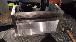
IMG_1049.jpg

IMG_1048.jpg

I found a design on this forum (photo below) and would like to know how the brass bush slides move up and down and retain the threaded tommy bar bolt for up and down movement? I don't see any grub screw which would retain the bolt?

Any different design configurations and ideas would be much appreciated also.

P1000984.jpg
 
I found a design online (on this forum)and would like to know how the brass bush slides move up and down and retain the threaded tommy bar bolt for up and down movement? I don't see any grub screw which would retain the bolt?

Any different design configurations and ideas would be much appreciated also.

View attachment 162098


That's the George H Thomas roll, I've built 2 (- 1 std and 1 double size,) the top roll bush is not retained to the pressure screw in any way.
 
That's the George H Thomas roll, I've built 2 (- 1 std and 1 double size,) the top roll bush is not retained to the pressure screw in any way.

How does the sliding bush move up and down? or does the screw only apply downwards force? Therefore leaving the rollers always in engagement?
 
You do realise that is a pinch roll design and not pyramid?? ...........the screw only applies downward force and the gears ere always engaged, (there are 4 in the train) - look up the design on the web - Hemingway kits IIRC
 
You do realise that is a pinch roll design and not pyramid?? ...........the screw only applies downward force and the gears ere always engaged, (there are 4 in the train) - look up the design on the web - Hemingway kits IIRC

Thanks, I wasn't aware of the difference.

I will be sure to check the other design.
 
In the original "words & music" Geo. H Thomas said that he made his without inter-roll gearing and that performance was perfectly satisfactory for his needs despite having under half the driving power of a geared version. By my reading he felt that the gear drive should only be made if you found simple single roll drive inadequate which was most likely to be when the material being bent could only accept very low roll pressure. In the book ("Model Engineers Workshop Manual") version he reports that a correspondent had made both rolls identical with so he could put handles on both rolls should the standard drive be inadequate. Of course, in general, drive requirements may be easily reduced by easing back the deflection roller to reduce the amount of bend per pass. After all its not a super heavy duty device and a couple or three more passes are of little moment doing the jobs it was intended for.

I imagine that one reason for the simple pressure screw arrangement on the top roll was to make it easy to slip the roll out to remove a full or near full circle component. If the screw were captive in the sliding bearing it would not be possible to simply release the tension and swing the screw carrying bridge out of the way.

Remember that the feed direction should be reversed on alternate passes to pretty much remove the straight section at the beginning of the bend. Unlike pyramid rolls this pressure and deflecting roller design produces much less straight section at the beginning of the bend and pretty much none at the end which makes life much easier. Especially on smaller diameter relatively long work.

Clive
 
Last edited:
As I'm using the roller to create a corrugation pattern in foil, I require the up and down movement to be able to be able to adjust the depth of corrugation. I'm not using it to bend metal into a cylindrical shape.

I'm looking for different design ideas for the up and down adjustment.
 
Ah.

Quick'n dirty one that worked for me in a somewhat similar arrangement was to make the screw with a suitable size round disk on the end and hold it to the bearing carrier via a bolted on flat plate having a recess for the disk. The adjuster screw proper had to run in a threaded bridge piece bolted on to the sideplate rather a direct thread direct as in your design. If you get creative with push in pins or some sort of bolt on C slotted angle plate its possible to come up with something to take the lift forces whilst keeping the thread in side plate design but everything I came up with looked either too much work, not wonderfully effective or both.

Clive
 
Would it be possible to make the pocket for the bearing housing longer/deeper, drill a hole or two holes in the frame and install springs to force the bearing block UP. The adjuster for the top roll takes the load and sets the opening height of the rolls while the spring or springs keep the block pushed UP, against the adjuster, which allows the two rolls to always open up when the adjusters are opened. Does that make sense?

How to you sync the two rolls so a 'ridge' on one roll it timed with a 'valley' on the other?

Stuart
 
imo the pinch is preferred, only a flat on the trailing end and they are great for flattening sheets - if you have a sheet with a few dings and bruises you run it through in different orientations with the two rollers tight and pinch roller out of the way and it restores it.

regardless, a small manual roller of either style are only going to work on very light gauge stuff

here's one I made eons ago. I was lavish with the brass because I was new and it was cheap(er), The upper portion of the block on the left where the top roller is held is removable to get the work out. it has a duty cycle of 10^-6 but helps hold down a shelf under the bench.


As I'm using the roller to create a corrugation pattern in foil, I require the up and down movement to be able to be able to adjust the depth of corrugation. I'm not using it to bend metal into a cylindrical shape.

Got a drawing of the finished product ?
 
imo the pinch is preferred, only a flat on the trailing end and they are great for flattening sheets - if you have a sheet with a few dings and bruises you run it through in different orientations with the two rollers tight and pinch roller out of the way and it restores it.

regardless, a small manual roller of either style are only going to work on very light gauge stuff

here's one I made eons ago. I was lavish with the brass because I was new and it was cheap(er), The upper portion of the block on the left where the top roller is held is removable to get the work out. it has a duty cycle of 10^-6 but helps hold down a shelf under the bench.


Very nice work, where did you get the gears from?


Back
Top