Hi all,
I’ve just commenced working with a fabrication company. We receive a lot of sheetmetal requests from customers and while I have some experience of basic sheetmetal design on SolidWorks I am not up to speed with fabricating it and all the nitty grityy things to consider.
I received a set of drawings from a customer recently and need to calculate my blank size (total flat pattern size) which I believe is based on the outside dimensions minus the material thickness. I can’t seem to find a standard formula to verify this.
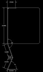
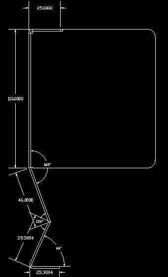
In the attached image for example (apologies for poor quality) would I need to do the following:
• Subtract 1.5mm from the top horizontal 25mm dimension
• Do I subtract thickness again from 110mm?
• I believe for the 46mm dimension I subtract 2/9 of thickness from 46mm
• Not sure about the 39.38 or the 23.38
Perhaps one could point me in the direction of a good Youtube video?