Peter S
Diamond
- Joined
- May 6, 2002
- Location
- Auckland, New Zealand
A machinist friend who has an interest in blacksmithing and old machinery recently pointed out a couple of marvellous examples of forging, seen in the photos of a George Watkins book "The Steam Engine in Industry vol 1".
I particularly like crankshafts forged from round stock - and here is a fairly massive (9" dia) example.
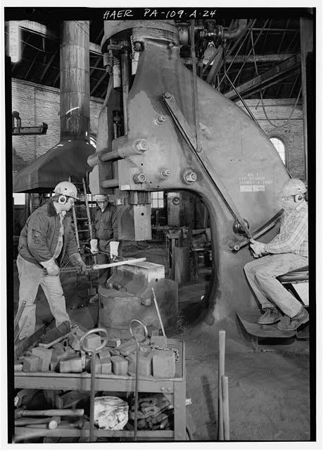
I can't say such knowledge is lost, but how would such a shaft be forged so tightly and neatly?
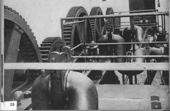
The photo was taken in 1935 and shows the pumps in Southhampton Waterworks. They were driven by a Easton and Anderson rotative beam engine. They were built in 1879.
"The crankshafts were splendid examples of smiths work, in wrought iron 9in diameter machined only for the pump rod bearings, which had a collar forged on either side of the brasses".
And a bit more about the pumps:
"Each engine drove by a cast iron pinion 3ft in diameter to a mortise gear 6ft in diameter upon the pump crankshaft. the teeth were 9in wide, those of the larger mortise wheel being made of apple wood, with twin tails passing through slots in the rim, and held in place by round pins driven through the tails. the teeth were lubricated with a mixture of blacklead and tallow, the central platforms giving access for this and to the oil holes in the top brasses of the pump connecting rods."
The pumps were 8 1/2in x 2ft stroke.

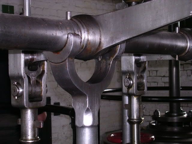
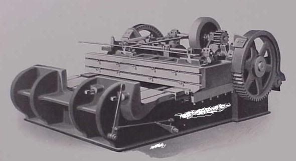
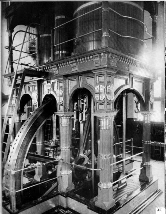
The next photo shows a beautiful inverted vertical engine built in 1890 by Robert Daglish for St Helens Waterworks. It has cylinders of 35 and 60 inches, with a 6ft stroke.
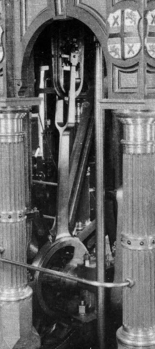
What interested us in particular is the eccentric rod forging, which the third photo shows closer up.
"The eccentric rods are fine forgings with the rod, forked top-end, and the top half of the eccentric strap in one piece."
Try and make that! The flywheel is 16ft in diameter, so the eccentric rod is around 7-8ft long.
I particularly like crankshafts forged from round stock - and here is a fairly massive (9" dia) example.
I can't say such knowledge is lost, but how would such a shaft be forged so tightly and neatly?
The photo was taken in 1935 and shows the pumps in Southhampton Waterworks. They were driven by a Easton and Anderson rotative beam engine. They were built in 1879.
"The crankshafts were splendid examples of smiths work, in wrought iron 9in diameter machined only for the pump rod bearings, which had a collar forged on either side of the brasses".
And a bit more about the pumps:
"Each engine drove by a cast iron pinion 3ft in diameter to a mortise gear 6ft in diameter upon the pump crankshaft. the teeth were 9in wide, those of the larger mortise wheel being made of apple wood, with twin tails passing through slots in the rim, and held in place by round pins driven through the tails. the teeth were lubricated with a mixture of blacklead and tallow, the central platforms giving access for this and to the oil holes in the top brasses of the pump connecting rods."
The pumps were 8 1/2in x 2ft stroke.
The next photo shows a beautiful inverted vertical engine built in 1890 by Robert Daglish for St Helens Waterworks. It has cylinders of 35 and 60 inches, with a 6ft stroke.
What interested us in particular is the eccentric rod forging, which the third photo shows closer up.
"The eccentric rods are fine forgings with the rod, forked top-end, and the top half of the eccentric strap in one piece."
Try and make that! The flywheel is 16ft in diameter, so the eccentric rod is around 7-8ft long.