What's new
What's new

10 degree modified square thread

antmob

Plastic
Joined
Jun 9, 2011
Location
San Jose, CA
Hello!
I have to make a part which calls out for a 3.5"-11 10 degree modified square thread (interal). I have no information about this type of thread other than what is in the 28th edition of the Machinery's Handbook page 1849. What I've figured out so far from the little information in the book and that the thread is 11 threads per inch (.0909 pitch) is that the root would measure .0494, the crest would measure .0415 and the height would measure .0454. I still don't know the major diameter of the internal thread. I'm not certain if my calculations are correct either. Can anybody offer any more information on this? Any would be greatly appreciated!
 
I cut modified square threads for a proprietary device. That said, it is not necessary to fit anyone's parts but my own.

I believe you have to add .010 to the tooth depth for clearance.

This makes the crest (as you state) .0415
Depth is .04545 + .010 = .055
root = (tan 5° x .055 x 2) + .0415 =.0096 +.0415 = .0511
Tip of threading tool width is going to be pitch - root =.090909 - .0511 = .03991" = .040" practically.

By what i have used, the ID/bore of the "nut" would be the OD male thread - 2 x .0454545 = OD - .091" since the clearance (.010) is already spec'd on the male thread. From what I have understood, the radial clearance is on both parts, IOW same tool used for ID/OD. Compared to acme threads, this would yield a flank bearing thread. Possibly like acme there may be a centralizing form used in some apps. I do not know. If this is to a print, the customer should specify.

Subject to correction by more experienced observers and worth every penny paid. :D

squarethreadtaps.jpg


smt
 
Thank you so much for you input Stephen. It is very much appreciated. I will use .01" as clearance as you mentioned. I did not get any information regarding the screws dimensions so I'm just going to have to hope that the part I make will fit. By the way, the call out for the thread on this part states that it is a 3.5"-11 internal thread. Does this mean that the minor diameter on my part should be 3.5"?
 
No you'll have to back figure to get the minor. 3 1/2 will be the major. Thread hight plus the clearance X2 subtracted from the major should give you the minor dia.

Brent
 
That is a good idea! How do you use wires on an ID?

Brent

You don't, you make a plug. I supposed one could use gage balls and some patience with an adjustable parallel or stack of jo blocks.

Side note- anyone know how to hand calc that? IE- how deep would a ball of certain size fall into a cone of a certain angle (your thread flank angle).

Hell, apparently I already learned and forgot this.

http://www.practicalmachinist.com/vb/metrology/measuring-taper-gage-balls-271629/

All you need are 3 appropriately sized pins, 2 of which need to be matched, and a micrometer.
Taper Measurement Using Gage Balls | Math Encounters Blog
 
Thread wires on a 10 degree thread? A caliper or worse yet, a micrometer which has the mechanical advantage of a screw thread, will just jam those wires down the Vee. Unless you have an awfully delicate touch, any reading you get will be +/- 0.010" or more. And any roughness on the surface of the thread will be multiplied by a factor of 5 or more.

Good luck with that. I would grind the thread cutting tool to the width spec and plunge it into the stock the required distance. Measure the major and minor diameters and when they are right, call it done. Be sure to include that extra clearance you subtract from the minor diameter.


CAD and thread wires should get you a reasonable check.
 
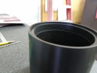
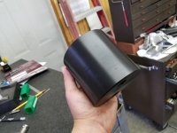
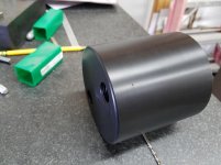
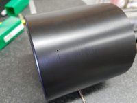
Hi everyone. Id like to thank everybody for their help and input on my question. Here are some pictures of the finished part.
20170213_131836.jpg20170213_131920.jpg20170213_131953.jpg20170213_132012.jpg20170213_131718.jpg the finished part and the cutter we ground.
 
Yeah me neither, I'm not even sure I see exactly how this works let alone know what What is it? Stupid question but you see nothing in the MH?

A female nut screws on making it collapse on a shaft? Kinda looks like a hose barb a little. I can't tell by the picture but the original looks to be machined and not cast? Knowing what it is might help folks help you figure out the thread.

Brent
 
What you have is different from what the OP posted about in this thread. It looks like the 10deg on your thread is 10deg off parallel to center line. His is 10deg perpendicular to the center line...J/S

Brent
 
I have seen similar features on devices that require field assembly and disassembly with near absolute holding power with some amount of adjustment to position. Looks like you are doing good so far.

today is 02022020 radar date
 
I have seen similar features on devices that require field assembly and disassembly with near absolute holding power with some amount of adjustment to position. Looks like you are doing good so far.

today is 02022020 radar date

"clockable"

1/2-28 is an important detail for sure.
 
Hi All,
I have a similar problem. I have never seen a thread like this (original shown.) The top angle measures 10 degrees. The male thread is slotted and the female thread is tapered to tighten down on a threaded shaft. The 10 deg-14 male thread is .625". The female thread has a taper and has a .002" tolerance to grab the 1/2-28 threaded shaft and bottom out the nut. I don't have a picture of the nut but will try to get one.

WAZP

View attachment 277338

It's a buttress thread. The MH book has plenty about buttress threads, at least mine did forty years ago. We made a lot of parts that were made of carbon (molten metal pumps). Many of them look similar to the parts by Antmob in post #12. Our engineers were doing a lot of experimenting with push type threads and pull type threads, some with 7 degree faces.

JH
 
WAZP I wonder if your part is designed to grab and hold a part when a sleeve is threaded on it, if the sleeve was made with a slight taper.


Back
Top