What's new
What's new

Adjust Pin Distance to modify Bucket Travel Skid Steer Quick Attach Fabrication

jimybuddiesel

Plastic
Joined
Jul 20, 2015
I am wanted to calculate how much additional distance I will need between pins to eliminate 1/2 inch of overhang of the quick attach when in the complete down position. A link to a formula or a math equation for calculation would be appreciated.

Assume the cylinder stroke is 12 inches.

Current pin distance is 6.3762

distance from the arm pin to the bottom of the quick attach is 2.25 inches.

below is some extra detail. I have also provide photographs to help with the explanation.


I am replacing my quick attach to the "bobtach standard". In the new system, when the bucket is all the way in dump position,it is impaired by the base plate. I would need another 1/2 distance for it to clear. The circle in the first photograph shows the issue point. The arm extends 1/2 inch past flush with the quick attach, and I would like to eliminate by lengthening the distance of the cylinder pin.

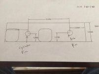
Currently the distance between the two pins is 6.3762. I am assuming that moving the cylinder pin further from the arm pin, assuming the cylinder stroke is constant will eventually eliminate the 1/2 past flush current issue. The second photograph is shows a side view of pin location and distance from pin,and also side view measurements of the proposed quick attach.

The tractor is in the field, so I can not get an accurate measurement of the stroke, but I believe it is approximate 12 inches.
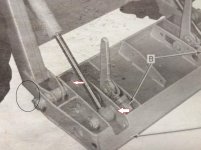
IMG_0944a.jpg

IMG_0946.jpg
 
Unfortunately formulas don't always work.

A formula will give you a distance between points.

When dealing with fabrication, or modification of existing designs, it's imperative that you do a hands-on physical setup to see where stuff actually goes, and how it fits.

Here we have the fitup on a grapple that's under construction.

heavy duty hinges43.jpg The final geometry has to be such that the grapple will close at the desired angle, but the body of the cylinder must not interfere with the structure. A formula will give you the point-point distance between pins, but it won't give you any idea how the cylinder diameter is located along those points. This a preliminary fitup with a hinge ear that's actually for use on another part of the machine, but it's a good start for finding what ya got goin' on. Measurements were taken, and the actual ear to be used in this location was made (pin height had to be altered)

Final geometry was determined. Pic is tilted for ease of viewing the angles (posted something somewhere about hydraulic force of cylinders mounted at different angles, and this made it easier to comprehend) Notice that the rod end pivot is just tacked at this point. Don't commit till you're happy.

heavy duty hinges74.jpg

I'm thinking, that in your situation, the pin that's gonna be easiest to move, is the one on the base of the cylinder. If it's like most loaders, it's probably a pin that's mounted between ears on the loader arm. That pin will have to be moved rearward. Disconnect the pin, and place blocking under the cylinder so that you can move it to approximate just where optimum geometry is attained. Then cut some new ears, remove the old ears from the arm, and clamp your new ears to the arm. Clamping allows you to still move the new ears before tacking them in place. Once you're satisfied, weld 'er up.

It might be unfeasible to completely remove the old ears. In this case, cut them off just above the arm, and fabricate new ear "scabs" that will fit in place of the old ears. These will simply overlay what's on the arm without having to cut off all the steel on the side of the arm. Laminating the area of the new ears, so that they will match the original span between the ears.

I think it's an easy job, but not one you can do from your armchair, or sitting in front of a puter punching in numbers. Not trying to be an azzhole, it's just that I do this kinda stuff on a pretty regular basis, and know what works for me.

NOW GET OUT THERE AND BURN SOME ROD!!!!!!!!!!!!!!!!:D:D:D
 
I'm sorry, but I'm not understanding your problem.


A couple of circles isn't doing it for me.
 
Last edited:
Thank you for the response.

My particular project is not that important, it is the geometric calculation that I am after.


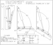
this image was borrowed from the internet. The second two drawing give a general idea of what i am trying to figure. there is an arm pin and a cylinder pin. in drawing two the swing radius of the thumb is 90 degrees and in the third it is 117 degrees.

On my application, I would like to increase the distance of the two pins to decrease the distance of the swing radius and am looking for the calculation.

Spend a bit of time researching concepts: arc length, arc pivot with two points. Again, looking for a geometric calculation.

ht2458-hydraulic-excavator-thumb-4.jpg
 
Still clear as mud to me.

You want less tilt of the bucket? Why not just decrease the cylinder stroke? If you can explain that then maybe we can get a better grasp of what you're after.

Basically, I would model this in 3d CAD with two models, one at closed cylinder and the other at extended cylinder and then check for interference of the cylinder or shaft with frame components.

It's a "School Project" we don't do "geometric Formulas"

We herd electrons on the screen to do what we want.

Do you have power steering in your car ?

We have "power steering" on our desk, to finger these things out.

Unlike finance people....:skep:
 
It's a "School Project" we don't do "geometric Formulas"

We herd electrons on the screen to do what we want.

Do you have power steering in your car ?

We have "power steering" on our desk, to finger these things out.

Unlike finance people....:skep:

3d models let you see other issues that may arise alongside a redesign issue that a simple formula addressing only one aspect will not. In this case, figuring out where to move pin holes to make a full stroke cylinder have a shorter travel sounds like nonsense. Moving the components around in 3d is the quickest way to address the issue.
 
3d models let you see other issues that may arise alongside a redesign issue that a simple formula addressing only one aspect will not. In this case, figuring out where to move pin holes to make a full stroke cylinder have a shorter travel sounds like nonsense. Moving the components around in 3d is the quickest way to address the issue.

You don't say ?......:D
 
Thank you for the response.

My particular project is not that important, it is the geometric calculation that I am after.


this image was borrowed from the internet. The second two drawing give a general idea of what i am trying to figure. there is an arm pin and a cylinder pin. in drawing two the swing radius of the thumb is 90 degrees and in the third it is 117 degrees.

On my application, I would like to increase the distance of the two pins to decrease the distance of the swing radius and am looking for the calculation.

Spend a bit of time researching concepts: arc length, arc pivot with two points. Again, looking for a geometric calculation.

View attachment 242216
Look up the law of cosines. Once you get the angle you want and the cyl. pressure. You’ll be able to calculate the force of the top lid.
 
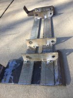
I took the advice first offered to mock it up and see how it fits and look for any obstructions or other issues. I used 1/8 inch stock for the mock up. This exercise will also give me a bit of experience for when I work with the .375 thick material.

took about an hour to complete.

The tractor is in the field so I will get to it tomorrow and see how it looks.

below are a couple of photographs of the mock up.

Thank you once again for the advice.

IMG_0952.jpg

IMG_0951.jpg
 
The best approach is to lay it out on a drafting board or in CAD. When you change the cylinder attachment point to get the "down" position you want it is also going to change the "up" position. It is much easier to work this out on paper or in CAD than to do it with trig.


Back
Top