What's new
What's new

Al on Al shrink fitting tolerance and torque transmission

Leiurus

Plastic
Joined
Jan 9, 2021
Good evening gentlemen

I am neither an engineer nor a machinist (and I think it will shows in my post...) but being a designer with 20yrs of XP in construction and a custom motorcycle builder, I have a vague idea of how things work, or should work.
It also give me a certain form of realism that makes me realize that I'm out of my league on this one and that I need help.

In my previous project, I designed a motorcycle real wheel spoke hub and got it CNCed from a block of T6. Great experience, but it took ages to get the drawing right and it costed me a bomb, being a one-off part.

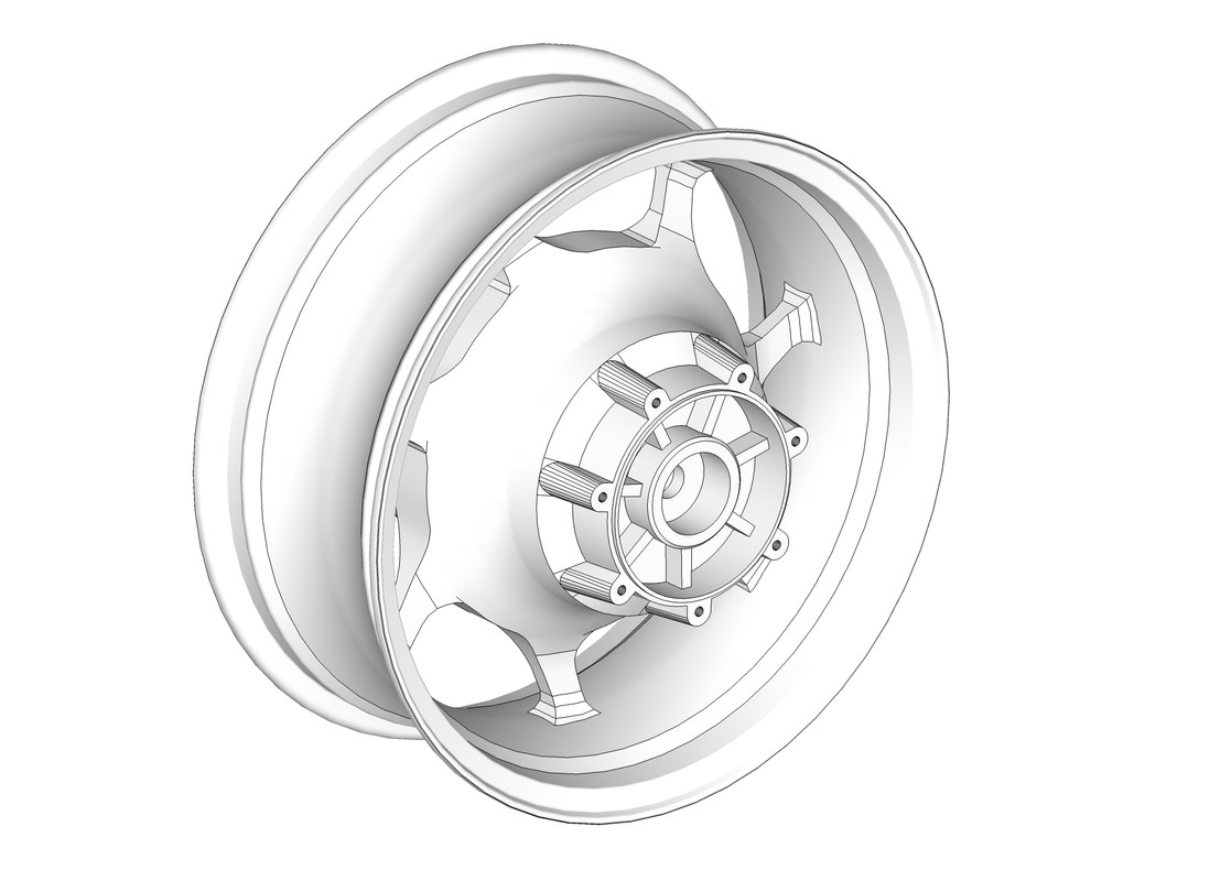
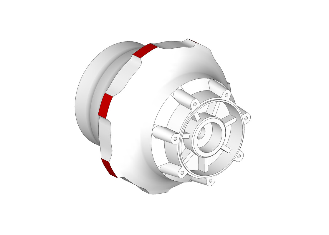
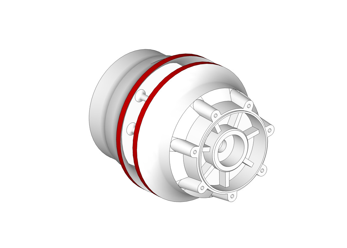
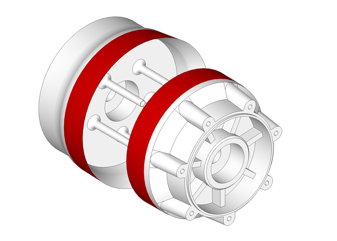
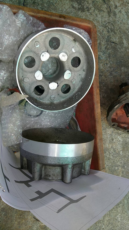
I'm working on a new project, and I'm trying a more conservative approach, which is basically pressing the drive and brake elements of an existing wheel into a fairly simple, lathed T6 "tube".
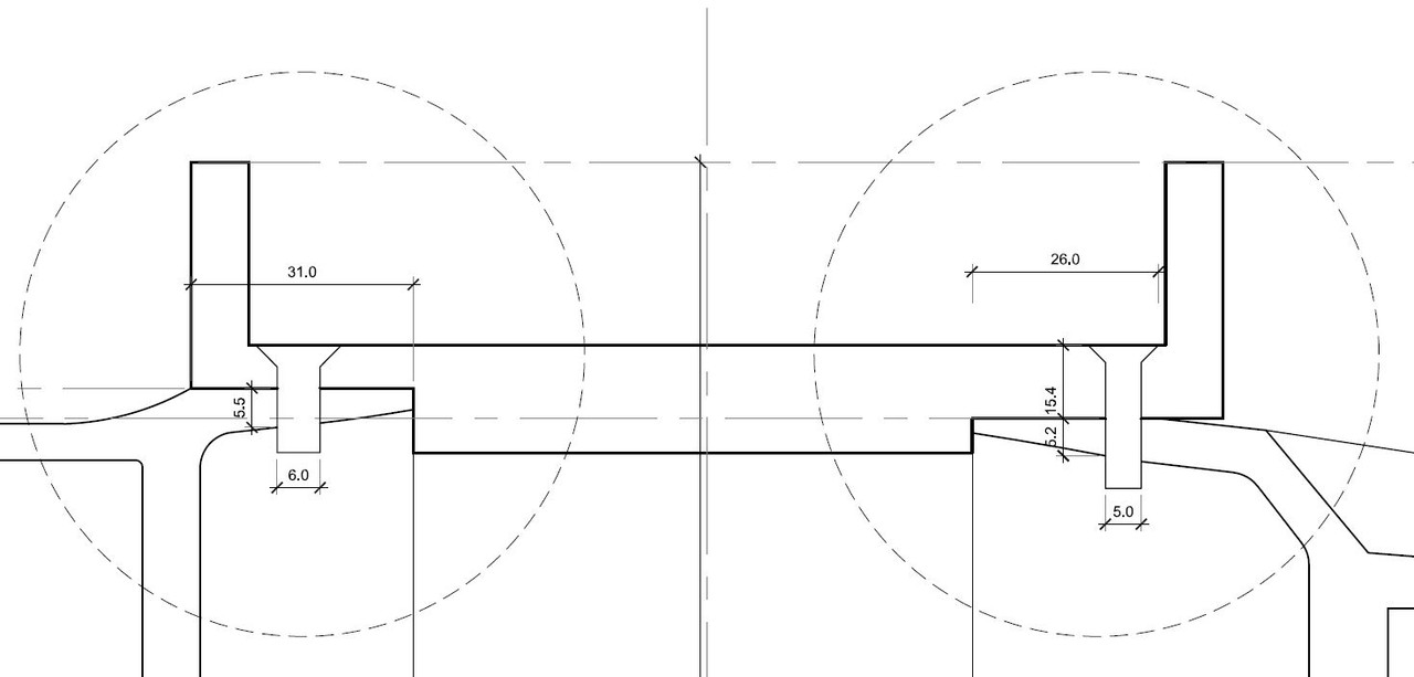
I got some drawings, etc...and I've already started to lathe the Drive / Brake, but I need a POC and would love to hear your advices / input.
I did my best to find the relevant informations by myself (which is why, for instance, I dropped the press-fit idea for a shrink-fit due to al galling), but I can't get the online calculators I've found to work...

Let me try to break it down in basic info:

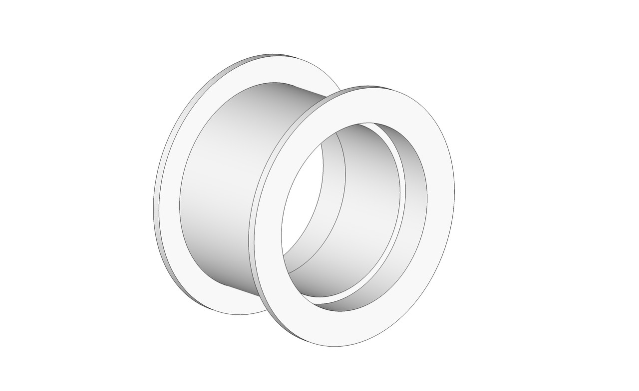
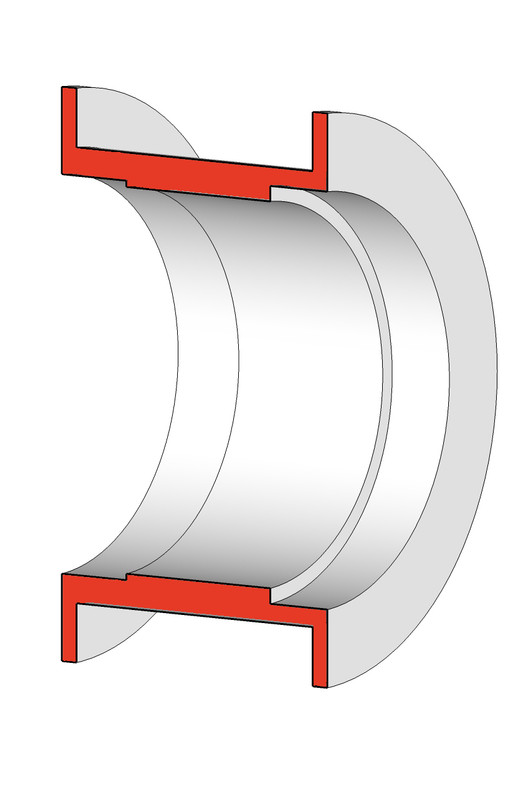
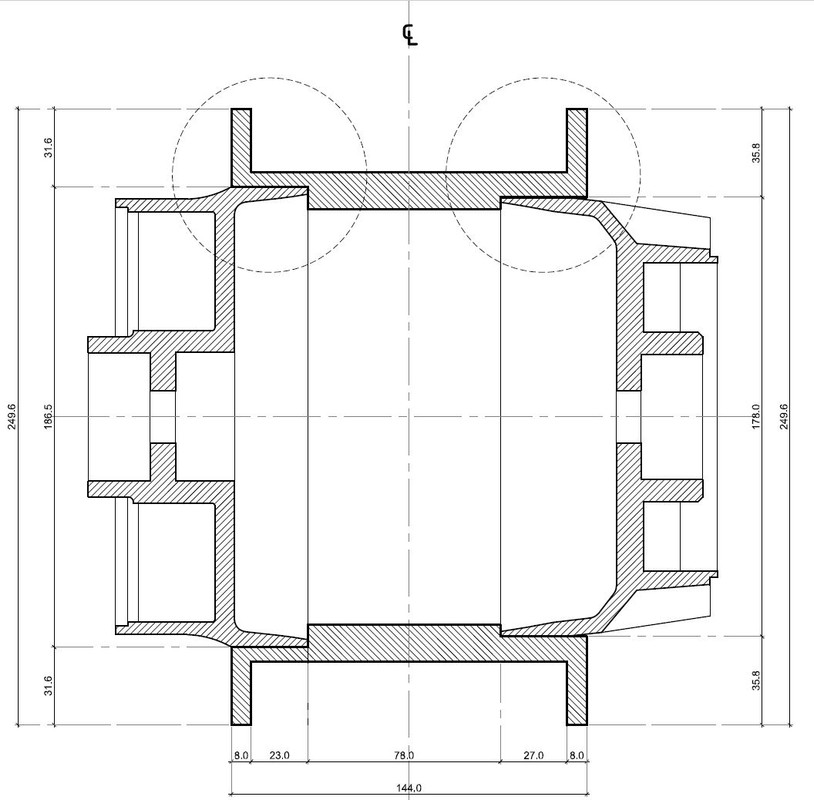
- shaft would be T6 al, 180mm OD, 7mm wall thickness
- Hub would be T6 as well, 180mm ID, 245mm OD
- Engagement length would be 30mm

The idea is to shrink fit the two parts after bringing the Hub @ 100C (by boiling it) and the shaft @ -70C by dumping it in dry ice. I estimate the actual temp of the two pieces to be 80C for the Hub and -50C for the shaft, even if I move fast during assembly.

My questions are:

- Does it have a chance to succeed of am I setting myself up for failure?
- What should be the max and min diametrical interference?
- If I were to select the median between max and min diam. interference, what max torque could the assy handle?

The idea here is to sort out if the assy:

- is realistically doable
- Has any chance to withstand the torque forces of acceleration / braking without additional operations. If it's a lost cause then I guess that another option would be to dutch pin the assy but it would be quite tricky due to the shape of the parts. Sure thing is that I want to avoid welding because on such a circumference, it's pretty much a given that a substantial area of the assy would reach annealing temp.

I'm really embarrassed to bother you with questions that are probably very dumb, but as stated above, I'm just out of my league...
 
I've dropped the idea of the assy interference withstanding the whole torque forces applied to the hub, and instead have opted for an array of threaded pins to secure the parts.

I nevertheless need a tight fit with a certain level of interference between the parts.

I intend to boil the hub to bring it to 100C, as mentioned earlier, and to submerge the shaft in a bath of dry ice + acetone or dry ice + alcohol (I would prefer alcohol for smell / volatility reasons but it seems that acetone works better...) which should bring it to -70C.
I think I can attempt the assy within 10s of the parts removal of their respective hot and cold bath. It is a complete guess, without any scientific calculation behind it, but I assume that the parts will respectively 80C and -50C at the time of assy (please chime in if I have grossly underestimated this).

If I apply the formula:

Diametric interference = temperature differential x coef. of linear expansion x diameter before expansion

or

Diametric interference = 130 x 0.000021 (taking the less favourable coef) x 180 = 0.4914mm

So let's say I play it safe and give me a margin of error, to make the assembly more forgiving, of 50%, that would be a Diametric Interference of 0.25mm

Does that sound right? Am I leaning towards a complete success (=drop fit) or an embarrassing failure (gross miscalculation leading to shaft stuck in hub half way, interference so low that the parts could be pulled off by hand, interference too high making the shaft crack, etc...)?
 
.25mm is a lot of interference for parts with a 180mm diameter. I would suggest thinking more about how the forces work on these parts, and what are the failure modes (what happens if they separate).

From that, start thinking about the tolerances you'll deal with with the two parts. You are unlikely to have perfect diameter control for every part you work with, so you have to plan for lesser and greater than ideal interferences too.

I'd suggest showing some design drawings here to get better advice on how to approach this assembly problem.
 
Thanks Milland

Here are some sketches / drawings to help you understand the concept:

The Drive and Brake sides of a stock cast Al wheel have been lathed. Process sketches:


And parts cut:


Next, the idea is to machine a Hub and to shrink fit them in. Hub sketch and section:


Concept section drawings with some dims in mm:


Then to pin the parts together with 6xM6 screws on the Drive side, 8xM5 screws on the brake side:
 
look at this or maybe find a better calculator:

https://www.tribology-abc.com/sub23.htm


Pa= f*3.142*d*L*Pc

where f=friction coefficient
Pc=contact pressure between the two members
d= nominal shaft dia
L=length of external member.
Pa= axial force required to interference fit

to calculate Pc for a given interference use the formula:-

Pc=x/[Dc*[((Dc^2+Di^2)/(Ei(Dc^2-Di^2))+((Do^2+Dc^2)/(Eo*(Do^2-Dc^2))-((Ui/Ei)+Ui/Eo))]

where x = total interference
Dc=dia of shaft
Di = inner dia of shaft(this is zero for solid shaft)
Do= outside dia of collar
Uo=poissons ratio for outer member
Ui=poissons ratio for inner member
Eo=modulus of elasticity for outer member
Ei=modulus of elasticity for inner member

This formula for Pc will simplify if the materials are the same.
 
I'll start this by saying "I am not an engineer", and while I do mechanical design professionally, it's guided by experience ("gut"), and not calculations.

That said, I'm worried about the three-part assembly, both from a strength and fatigue life standpoint (thin cast Al parts mated to a heavier center cylinder), the localized stress aspect (each of the fastener points is a stress concentration), and the overall alignments of the three parts if still a vehicle wheel application.

Between those worries, and the preparation requited to split and modify the original wheel, I'd think that a "clean sheet design" might wind up being safer, stronger, and cheaper to accomplish.

With modern 3D printing capability, you might be able to model a new part, print a casting core from a low-temp plastic, and have a fresh part cast as a whole. That, or simplify aspects of the design to allow it to be machined from solid.

You'd still want to confirm that stress and fatigue life is adequate for your purpose, having wheels fail on a passenger vehicle is generally not a good thing...
 
As I understand your concept, your shrink fits have nearly zero strength. Dependable shrink fits need heavy sections, your cantilever section doesn't qualify.
 
I'll start this by saying "I am not an engineer", and while I do mechanical design professionally, it's guided by experience ("gut"), and not calculations.

That said, I'm worried about the three-part assembly, both from a strength and fatigue life standpoint (thin cast Al parts mated to a heavier center cylinder), the localized stress aspect (each of the fastener points is a stress concentration), and the overall alignments of the three parts if still a vehicle wheel application.

Between those worries, and the preparation requited to split and modify the original wheel, I'd think that a "clean sheet design" might wind up being safer, stronger, and cheaper to accomplish.

With modern 3D printing capability, you might be able to model a new part, print a casting core from a low-temp plastic, and have a fresh part cast as a whole. That, or simplify aspects of the design to allow it to be machined from solid.

You'd still want to confirm that stress and fatigue life is adequate for your purpose, having wheels fail on a passenger vehicle is generally not a good thing...

Well I guess we are on the same boat...

It's quite obvious that I'm not an engineer either, but I've been building a few bikes and I'm following my "gut" feeling as well, mostly with success so far, and by that I mean that I've never had a catastrophic failure.

My gut feeling tells me that interference fit only will almost surely fail and that pins only will certainly fail as well. But I do think that a decent interference "locking" and mating the parts together, with the pins not to structurally keep them together, but to prevent friction under torque, could work.

I totally agree that the best option would be to machine a solid block of T6. That's precisely what I did on my previous build, which turned out perfect, but it has also been a loooooot of work to get the model of the cush drive right and it didn't come cheap to CNC it...The brake side visible on the sketches is quite simple, but on the other side there are the pockets for the rubber dampers of the cush drive and these guys are hard to replicate without 3D scanner.

I also have the option to get a hub fabricated by a wire wheel builder, but without cush drive. Direct drive, with the pulley bolted straight on the hub. That's how Harleys work, but that's because they have the damping done by a compensating sprocket at primary case level. So if I go for this option, I'll have a fully rigid set up. I'm fine with snapping a belt here and there, but a bit worried by a premature wear of the transmission. The bike is a heavy cruiser, 815lbs wet and 130lbs/ft of torque.
 
Can I just say that even without a shrink fit, just being what we called a " size and size " fit, pressing an aluminium component into another aluminium component stands a pretty good chance of " galling up " on the way in.

Regards Tyrone.
 
look at this or maybe find a better calculator:

https://www.tribology-abc.com/sub23.htm


Pa= f*3.142*d*L*Pc

where f=friction coefficient
Pc=contact pressure between the two members
d= nominal shaft dia
L=length of external member.
Pa= axial force required to interference fit

to calculate Pc for a given interference use the formula:-

Pc=x/[Dc*[((Dc^2+Di^2)/(Ei(Dc^2-Di^2))+((Do^2+Dc^2)/(Eo*(Do^2-Dc^2))-((Ui/Ei)+Ui/Eo))]

where x = total interference
Dc=dia of shaft
Di = inner dia of shaft(this is zero for solid shaft)
Do= outside dia of collar
Uo=poissons ratio for outer member
Ui=poissons ratio for inner member
Eo=modulus of elasticity for outer member
Ei=modulus of elasticity for inner member

This formula for Pc will simplify if the materials are the same.

Many thanks for that. I knew the calculator but was lacking the info you listed, thanks again.

As I understand your concept, your shrink fits have nearly zero strength. Dependable shrink fits need heavy sections, your cantilever section doesn't qualify.

I'm not sure I understand, what do you mean by cantilevered? It's basically a tube fitted in a tube, I probably understand "cantilever" wrong because the way I understand the term, I can't find anything cantilevered in the assy.

Can I just say that even without a shrink fit, just being what we called a " size and size " fit, pressing an aluminium component into another aluminium component stands a pretty good chance of " galling up " on the way in.

Regards Tyrone.

Yes, that's what I've read and the reason for attempting a shrink-fit instead of a press fit. My understanding is that the Al galling during a press fit is caused by the combination of the friction and the material elasticity. Shrink fitting, I assume, should nullify the friction since it would be, ideally, a drop fit. Same concept than dropping a frozen bearing in an Al hub heated at 100C.
 
Shrink fit tolerance for aluminum bushing in cast aluminum bellhousing?

I have a cast aluminum bellhousing for which I need to make an aluminum bushing to fit a transmission with a smaller pilot into.

The bore of the bellhousing is just under 5", and I need to reduce that to about 4.5". ((I'll supply exact measurements later).
The bellhousing is about 3/8" thick at the bore, and I plan to machine a groove of .100" width and depth into the bellhousing, and a corresponding step in the bushing, to prevent the bushing from pushing all way through.

My question is how much interference should I provide in order to freeze the bushing to about 0 deg f, to allow it to drop into the bellhousing at near room temp (I can set it in the sun to warm up)?
The interference doesn't need to be extremely tight, as it's only to locate the pilot, and to prevent the bushing from pulling out when the transmission is removed for maintenance.

Also, how much clearance on the bushing ID, to allow the steel pilot to slip into the bushing without interference?
Do I need to provide additional clearance to account for a difference when it's shrunk into place?

I know this is a lot of questions, and thanks in advance for any help.
David
 
I'd use about .002" interference Al/Al for 5" with the temp delta you're describing. A 70 degree F temperature delta gives about .004" of shrinkage, so you'd have .002" clearance, so make sure you go in straight.

Here's a CTE/distance calculator to check for yourself:

Thermal Expansion Calculator - Good Calculators

I'd also go with .002" as clearance to the pilot at room temp, so the free inside diameter of the ring should be around .004" larger than the pilot diameter.

I'd be certain the steel pilot is clean, very smooth, and with a nice entry chamfer with no nicks to catch on installation. If you can't install and remove the pilot in a straight line, increase the final clearance. A little anti-seize on the pilot will help prevent galvanic corrosion and locking over time.

And now you have me wondering how the wheel guy (OP) did...

Thank you Milland.
With one post, you thoroughly answered all my questions. That's the kind of help anyone would hope for. :D

Have a great evening, and I'll post my results back here when I get it all finished.

David
 
If I were to do it I would drill and tap a pattern of holes directly on the joint and thread in set screws. This prevents slip in all directions.

Having just read more of the posts I realize that's not an option on these thin sections and you are already pinning them, but it's a useful tip for press fit hubs in general.

I would think you need an anti crush tube between the two bearing seats to better handle axially loads and provide nonspringy preload to help with bearing life, but I have little experience with what you are trying to do.
 
Now that's a coincidence, I came back to this thread precisely today to check it before bringing the hub to the machinist for a second pass.
I'll elaborate more tomorrow, just wanted to drop a few lines today because it's so weird that the thread came back to life the very same day I'm looking at it after months of inactivity. In a nutshell, no, I'm not gone, life just got in the way but the project is back at the top of my to-do list.

Well, we're glad you didn't die when a wheel came apart in traffic...

;)
 
I have a cast aluminum bellhousing for which I need to make an aluminum bushing to fit a transmission with a smaller pilot into.

The bore of the bellhousing is just under 5", and I need to reduce that to about 4.5". ((I'll supply exact measurements later).
The bellhousing is about 3/8" thick at the bore, and I plan to machine a groove of .100" width and depth into the bellhousing, and a corresponding step in the bushing, to prevent the bushing from pushing all way through.

My question is how much interference should I provide in order to freeze the bushing to about 0 deg f, to allow it to drop into the bellhousing at near room temp (I can set it in the sun to warm up)?
The interference doesn't need to be extremely tight, as it's only to locate the pilot, and to prevent the bushing from pulling out when the transmission is removed for maintenance.

Also, how much clearance on the bushing ID, to allow the steel pilot to slip into the bushing without interference?
Do I need to provide additional clearance to account for a difference when it's shrunk into place?

I know this is a lot of questions, and thanks in advance for any help.
David

You don't need or want a press fit at all here.

The hole in the bellhousing has a chamfer on it. Use it. Make your sleeve with a small lip to nest in the bellhousing's existing chamfer.

I would mic the bore in several places because they usually aren't perfectly round and make my sleeve about .0005" to .001" under the average size of the bore so it pushes in.

If you want it to stay in place put some green loctite on it.
 
Alright, so no, I didn't die in traffic either :D

Long story short, it took me ages to source the bloc of Al for the hub machining, then life got in the way and I sat on it for a solid couple of months. I took it out of its wrapping yesterday, and here it is in his shiny glory:


The rims for the spokes are a tad over dimensioned to leave me some slack when the wheel guy and I have sorted out their final height / thickness.

The plan has already slightly changed, and I guess it's not too stupidly planned since pretty much everything I have in mind have been mentioned in the latest posts ;)

- I will be a bit more modest in the interference, bringing it down to 0.15mm from the originally planned 0.25
- If I managed to shrink fit both sides, I will then indeed tap set screws. There's not much meat left in the brake / drive sections there (approx. 6mm) but they won't bear the brunt of the load.
- The final step will be to weld at the contact between hubs and the brake / drive sections

Currently the diameters of the seats on each side of the hubs are a few mm smaller than needed. I get it machined "step by step" because communication is challenging with the language barrier. I can shave off some material but not add any, so the next step is to bring it back to the machinist and to get them enlarged to the right diameters to attempt the drop fit.

@Strostkovy: there is a steel tube between the two bearings, that's standard bike wheels construction, it's just not shown on the drawings.

Thank you all for the inputs, keep them coming, on my side I'll keep posting updates as the project goes


Back
Top