What's new
What's new

Anti vibration coupler

Cyborg

Aluminum
Joined
Jun 16, 2019
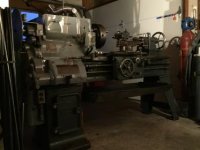
I am trying to reduce the vibration in an old McDougall lathe. Long ago it was converted from belt drive to direct drive. The motor is mounted vertically in the base under the headstock and connected to the input shaft with something similar to
McMaster-Carr
There is some misalignment, which can be reduced, but wondering if there is a different style coupler on the market that will tolerate some misalignment and hopefully reduce vibration. After the original modification was done, the motor was replaced with a larger one. The size of the motor and the way it is mounted make it very difficult to line up the motor perfectly. Any suggestions would be appreciated.

594E542A-1847-47EB-B3DF-B0AC3569A515.jpg
 
That coupling already has a rubber center and provides significant damping and misalignment capability compared to a lot of other couplings. What is the evidence that the coupling is the problem? Is it possible some shaft is just plain bent? Is some sheave wildly out of balance?
 
It’s a little awkward getting in there with dial gauges, but I checked the runout on the motor shaft and it’s ok, same with the lower half (drive side)of the coupler. When I checked the upper half (driven) of the coupler it seemed to be out by a total of approximately.014”. I marked the high spot with the idea of moving the motor over .007, but I noticed that when rotating the coupler about 25 degrees it dropped to zero. That suggests something is wonky with the upper half. I could just forget about the runout on the upper half of the coupler for now and run the indicator off the shaft and adjust the motor mount based on that. Only thing is, adjusting the motor will probably send me off the deep end, so thinking maybe a new, better? coupler before I start.
As a crude test, you can put a piece of stock up against the lower half while it’s running and there is no noticeable runout. Put the piece of stock against the upper half or the input shaft and the piece of stock bounces around quite a bit.
If I was machining parts to look like corncobs it wouldn’t matter. The vibration telegraphs through the cutting tool. The alignment is definitely out, but the coupler is suspect as well.
Not sure what you mean by sheave. There are no pulleys. From the coupler, the shaft goes up to the headstock and direction is changed via a crown and pinion differential that was borrowed from a VW. From there it goes through a VW 4 spd synco gearbox. Strange, but true….
 
That type of coupler is commonly used on drives up to about 75 hp. They do not require the precision of a dial indicator alignment. All that's needed is a straight edge and feeler gauges. If you want more precision you still start with straight edge and feeler gauges in order for your indicator reading to start close to where it should be. There is a procedure for taking face and rim indicator readings and then calculating shim amounts to bring shafts into proper alignment. Either method is difficult in tight quarters. Belt drive would lower vibration and alignment problem.
 
Ya but...you havent read the part where the drive includes half a Volkswagen.....a lot of scope for vibration/misalignment there .......incidentally,VW wheel drive is via a sort of a CV joint ,and the diff would need to be locked up somehow,too.
 
I suggest the OP get a real lathe.

Excellent suggestion. It’s crossed my mind a few times. The lathe was cheap and just the tool post, chucks, and portable milling machine that came with it more than justify the cost. There are a few issues with the lathe which may be worth fixing if I can sort out the vibration. I have another smaller lathe and basically bought this one because of its ability to remove metal quickly.
 
Remove / disconnect the coupling and see if the motor is out of balance

I’ll do that at some point, but from what I’ve seen so far, it doesn’t look like the problem is the motor itself. Other than it’s single phase.
 
Ya but...you havent read the part where the drive includes half a Volkswagen.....a lot of scope for vibration/misalignment there .......incidentally,VW wheel drive is via a sort of a CV joint ,and the diff would need to be locked up somehow,too.
There is just the crown and pinion…. no spider gears. I actually wondered about a CV joint, but they can cause vibration problems too. Maybe I’m fooling myself, but looking for a relatively easy fix. If it gets too involved then I’m better off taking Steve’s advice.
 
How much horsepower are you working with?

Good question. I don’t know. The motor is squeezed in there and even with a bore scope or mirror, I can’t see the plate. It runs off 220 and came with some fairly hefty cable. Running off a 30 amp breaker which works. Bride claims the lights upstairs dim when I switch it on. Assuming it is either 5 or 7.5 hp.
 
That type of coupler is commonly used on drives up to about 75 hp. They do not require the precision of a dial indicator alignment. All that's needed is a straight edge and feeler gauges. If you want more precision you still start with straight edge and feeler gauges in order for your indicator reading to start close to where it should be. There is a procedure for taking face and rim indicator readings and then calculating shim amounts to bring shafts into proper alignment. Either method is difficult in tight quarters. Belt drive would lower vibration and alignment problem.

Belt drive has also crossed my mind, but again, not a lot of real estate in there. Without relocating the motor somewhere else, I’d be limited to about 6” between centres on the shafts. Relocation of the motor might be the second best option.
 
I know this thing sounds strange and it is. The modifications were done long ago, presumably because of budget constraints. Although you could question the logic, the original modifications were well done. For example, the bearing in the headstock (assuming it was babbitt) was replaced with a pair of taper rollers and it’s still pretty much perfect. I’m only guessing, but I think the vibration problem arose either when a subsequent owner installed the larger motor or one of its moves resulted in some damage. The later is a distinct possibility. I can’t ask the fellow who installed the motor because he’s no longer with us.
 
I'm having a hard time picturing this thing :eek: But normally an automotive ring and pinion is optimized for the pinion to drive the ring gear in the forward direction. If it's driving backwards from that, with the ring driving the pinion ? Or even normally but with the pinion going the wrong direction ? I'd expect it to be extra noisy and rough. The teeth are now pessimized for that direction.
 
I'm having a hard time picturing this thing :eek: But normally an automotive ring and pinion is optimized for the pinion to drive the ring gear in the forward direction. If it's driving backwards from that, with the ring driving the pinion ? Or even normally but with the pinion going the wrong direction ? I'd expect it to be extra noisy and rough. The teeth are now pessimized for that direction.

Thing? Thing of beauty maybe. The crown and pinion seems quite happy and it turns in the correct direction… at least when the lathe is in forward. I’d wager a bunch of beer it’s a combination of the natural tendency of a single phase motor to vibrate, misalignment of the motor, and the coupler itself. The world must have a better coupler somewhere. Along with the lack of space, the setup for adjusting the motor is a bit of challenge, so if there is a better coupler then it would be nice to install it first.

Hard to make out, but gearshift lever sticking out the top is for the back gear High/Low range.

ADF79228-B72B-4716-BD37-04735AF10D4E.jpg
 
That type of coupler is commonly used on drives up to about 75 hp. They do not require the precision of a dial indicator alignment. All that's needed is a straight edge and feeler gauges. If you want more precision you still start with straight edge and feeler gauges in order for your indicator reading to start close to where it should be. There is a procedure for taking face and rim indicator readings and then calculating shim amounts to bring shafts into proper alignment. Either method is difficult in tight quarters. Belt drive would lower vibration and alignment problem.

Would be fine for a 75 hp manure spreader if you don't care about bearing life and such. On a machine tool that misalignment will show up as the OP has learned. It will also reduce the life of bearings and associated parts.any coupling that far out will transmit some pulse as it rotates. There must be a better way than half of a VW packed in there.


Back
Top