What's new
What's new

Any trig gurus on here?

Parkerbender

Stainless
Joined
Dec 19, 2009
Location
Kansas City Mo, USA
I knew I should have paid better attention in school... Ha.

Anyway,
So I have a part that needs tipped left 3.1716 degrees, and tipped back 2.777 degrees, and I am trying to add the angles so I can program this as a 3d cut on my mill as one 'x-z' angle, translated in 'y' but rotated at an angle about the c axis. Does that made sense? I can't remember even what the damn math procedure is called to relearn it, I believe we were doing this with a unit circle in school, but I start thinking and then my thermal overload trips in my head...
Anyone remember how to do this?

Thanks for any help at all!
-Parker
 
"Compound Angles" In the 27th edition of Machinery's Handbook, it's on pages 108-110. Have to imagine it's in every other edition of MH as well.
 
I'm not sure if this helps or not but for the first angle, 3.1716; the taper is .05541" per inch or .27706" per 5" length.

For the second, 2.777; the taper is .04851" per inch and .24253" per 5" length...
 
I knew I should have paid better attention in school... Ha.

Anyway,
So I have a part that needs tipped left 3.1716 degrees, and tipped back 2.777 degrees, and I am trying to add the angles so I can program this as a 3d cut on my mill as one 'x-z' angle, translated in 'y' but rotated at an angle about the c axis. Does that made sense? I can't remember even what the damn math procedure is called to relearn it, I believe we were doing this with a unit circle in school, but I start thinking and then my thermal overload trips in my head...
Anyone remember how to do this?

Thanks for any help at all!
-Parker

So if I'm understanding correctly (we'll get to the errors).

RED--Rotary needs to rotate CCW or -3.1716º then back to -.3946º ( rotated back 2.777º from 3.1716º)
GREEN--irrelevant to the problem, right? just substitute Y for X in the Graph
BLUE--this is the hard part. C Axis is technically "about the Z Axis" so assuming that you mean about the X that has been translated from Y. Which would be the A Axis. But you don't have a rotary, you are trying to do this just with XZ moves---right?

If all that is true, then we would need to know the depth of the Z to calculate the Hypotenuse. Now my head is starting to hurt. This is one of those times when CAD/CAM is very nice to have.

R
 
Honestly just draw it out as 2 seperate 2d problems, ie top and side on views, solve the simple right angle triangle math for each to give you the numbers you do not know then simply use those hypotenuse lengths to calculate your unknowns. Its kinda the simple way to solve 3d vectors.

Theres probably calculators online for this too, but breaking it down into 2 simple 2d triangles is way way easier.
 
I know Trig quite well but I'm also not sure what you want to do. I'm as lazy as most that have CAD. Draw it like previously mentioned and get the dimensions from CAD. Also most scientific calculators will do trig, probably get one at Walmart for less than $20. Most will do Polar Co-Ordnance too.
 
#8 Froneck
". . . scientific calculators will do trig, probably get one at Walmart for less than $20 . . ."

99.9% of phones, tablets or computers used to post on PM will already have a scientific calculator.
FOC downloads are available for the 0.1%.
 
A bit of info that has stuck with me. At least where to find it. From Suburban Tool.

This is about setting dual sine plates. To be honest, I don't know if this is relevant only to sine plates in particular, or compound angles in general.

"When setting compound angles, it is necessary to compensate for the first angle set in order to correctly set the second angle. Refer to the following drawings and procedures. The compensation will be calculated for you."

The link to instructions and an online calculator.

SUBURBAN TOOL, INC. - How To Use A Compound Sine Plate

If nothing else, it's interesting stuff.

Dave
 
Last edited:
...So I have a part that needs tipped left 3.1716 degrees, and tipped back 2.777 degrees, and I am trying to add the angles so I can program this as a 3d cut on my mill as one 'x-z' angle, translated in 'y' but rotated at an angle about the c axis. Does that made sense?
You lost me when you "translated" it in Y and "rotated" it in Z.

Compound angles, obviously the first angle changes the second one- sin(a + b) DOES NOT equal sin(a) + sin(b).

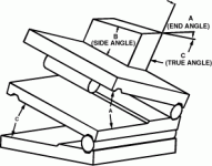
I don't know how you have the part oriented on the machine. 13 engines beat me to it, I also use the Suburban page for reference. This is how you would set up a compound sine plate:

Your first stack is just sin(a) x hypotenuse.

Your second stack is tan(true angle(c))=tan(b) x cos(a)

IOW, true angle (c) is what you would set the second angle on the sine plate, to get the correct angle b on the part. tan^-1(tan(b) x cos(a))=(c)

compound.gif

To hemstitch that on the machine, with the part sitting flat and square to X and Y- your gage block stacks represents the Delta Z (the short side of the triangle) in each axis over the X travel (the long side) of each angle, and your toolpath machines the hypotenuse.
 
"So I have a part that needs tipped left 3.1716 degrees, and tipped back 2.777 degrees, and I am trying to add the angles so I can program this as a 3d cut on my mill as one 'x-z' angle, translated in 'y' but rotated at an angle about the c axis"

This part is fixed at the bottom at x0, y0, correct?

Next, it is tilted to 3.1716 degrees in the x direction.

Then, tipped back 2.777 degrees in the y direction.

The bottom of this part is still located at x0, y0, but the top is x-?, y?.

You want the top of the tilted part rotated around x0, y0 until the top of the tilted part is x-?, y0, I think.

And you want to know what the compounded angle of x is now? If so, it is 4.2146°
 
Good thing smart people showed up, I was interpreting something different. I was interpreting motion or dynamics. My bad, Ignore post #4

R
 
If you are going to rotate a part by two angles that are on mutually perpendicular axis, then you MUST specify which rotation you need to do first.

And once you do find a combined angle, for some kinds of features you also must find out in which direction (angle in the horizontal plane) that that combined angle is to be measured in.

You do mention the left tilt first, but you do not say that is the order to do it in. 3D geometry gets confusing fast. Do play with it in 3D CAD. You should be able to dimension the angles there after making the rotations.

In short, you need to be a lot more specific.


I knew I should have paid better attention in school... Ha.

Anyway,
So I have a part that needs tipped left 3.1716 degrees, and tipped back 2.777 degrees, and I am trying to add the angles so I can program this as a 3d cut on my mill as one 'x-z' angle, translated in 'y' but rotated at an angle about the c axis. Does that made sense? I can't remember even what the damn math procedure is called to relearn it, I believe we were doing this with a unit circle in school, but I start thinking and then my thermal overload trips in my head...
Anyone remember how to do this?

Thanks for any help at all!
-Parker
 
Hey Guys,
Thanks for all of the replies, I ended up guessing and checking but got to where gary was in post 7 with the 4.2 and 41 degrees or so. (I actually got about 4.5 degrees down at 42.5 degrees turned, but I am sure that those other numbers are actually correct) this isn't under nda, so I'll get some pictures rounded up and show you what I was talking about. I am not the best at the 3d parametric stuff as it was all 2d cad when I went to school, and I was mostly just frusterated that I couldnt math through the problem with this stupid expensive schooling that I seldom use...

Anyway, have a great night, see ya in the morning!
-Parker

Sent from my SM-G950U using Tapatalk
 
I knew I should have paid better attention in school... Ha.

Anyway,
So I have a part that needs tipped left 3.1716 degrees, and tipped back 2.777 degrees, and I am trying to add the angles so I can program this as a 3d cut on my mill as one 'x-z' angle, translated in 'y' but rotated at an angle about the c axis. Does that made sense? I can't remember even what the damn math procedure is called to relearn it, I believe we were doing this with a unit circle in school, but I start thinking and then my thermal overload trips in my head...
Anyone remember how to do this?

Thanks for any help at all!
-Parker

Might be a good idea to take time to "relearn" if trig is something you'll use often.

This makes it easy for most things.

Trigonometry Calculator
 
So, those struts are tipped back a bit, and tipped towards each other a bit, and I was wanting to handle all of that in the one base plate without making a special fixture and creating a third op, so I needed to figure out what angles I needed to cut. Basically just a plane on the bottom that made the top flat and square with the world. Seems simple until you get your calculator out... at least for me!
d7c19e3874aec813076b5ef73e309a45.jpg
38f07283badff3878e8c986949202b55.jpg


Sent from my SM-G950U using Tapatalk
 
2nd try to post, something weird happened when using the "mobile" version of the page

you can eliminate both "angle problems" by allowing 1st the bar to be tipped backwards a bit (which doesn't affect it's function, just aesthetics), 2nd angle is solved in changing the design of the riser, if you don't want to tip the bar, the "odd" angle will be at the bottom of the riser, which complicates mounting it to the plate a little bit

p.s. those spacers under the plate is not a good idea, it is a very definitive weak point in the whole structure, if it was my project, I'd probably move the bar forwards, to clear the tank/hose above the intake, lower the bar and make the base plate a single part, L shaped looking from the side, mount the plates, put the bar in place, mark holes by hand, drill for screws and be done, can then measure where they were exactly to finalize the drawing for the part
 
Hey JZ,
Not sure what you would be doing by moving a strut brace from the top of the studs on the top of the struts to... the inner fender walls? If you move the brace off of that point it firstly runs into a whole lot of interesting sheet metal and no flat surfaces to mount to, and also the inside of the engine bay gets about 9 inches wider so a person would be trying to stiffen the strut mounts by means of a longer bar and 16 gauge steel...

Secondly, though I would love to have mounted the bar lower down on the studs, there needs to be clearance on the ends to account for the rebound adjustment of the shocks, and in the middle to clear the factory supercharger (not on this specific vehicle). Though it would appear weaker than the rest of the bar, a person has six m10's resisting the camming out of the risers there, if a person put a hook on it, you could lift about ten of these vehicles by that mounting arrangement, though the bar would only be good for that weight of loaded lengthwise (the way it's designed to be loaded).

Thanks for the feedback though! It is probably hard to tell much about the application from a grainy photo...

Sent from my SM-G950U using Tapatalk


Back
Top